Fabrication of ultralow-roughness surfaces: The Beilby layer
Surfaces having extremely low surface roughness (less than 1 Å RMS) are frequently specified by customers requiring increased optical and energy efficiency, with some of the most stringent requirements coming from applications in the UV, ultralow scatter, and high-power laser systems. Much research has been performed to understand the related surface dynamics, and a large amount of information has been published on precision finishing of optical glass. While many suppliers of low-roughness surfaces rely on traditional loose abrasive finishing methods that create subsurface damage (SSD) through the aggressive removal of material, a new approach is introduced that produces surfaces having little or no measurable SSD.
A method that is heavily dependent on surface chemistry and surface dynamics is used to continually create and remove a hydroxyl-rich diffusion layer in silica glass without disturbing the base substrate, thereby eliminating any determinate SSD. By focusing on incremental removal of small portions of the Beilby layer (explained below), near-perfect surfaces are created. This technique has been shown to produce excellent results in fused silica, borosilicate glass, silicon, and calcium fluoride materials.
Applications for optics having these properties are found in automotive, defense, medical, and industrial domains. Types of processes useful for achieving these results will be discussed. Metrology equipment and techniques for producing reliable sub-Angstrom measurements are discussed in a separate publication.
Much information has been published regarding removal mechanisms for fused silica and silicate glasses.1-4 Archard’s equation relates volumetric material removal to work performed by frictional forces; Preston’s equation is cited to calculate material removal rate as a product of pressure and velocity; Navier-Stokes equations provide expressions for compressible flow of viscoelastic materials based on inherent material properties and for establishing a relationship between interface stress, expansion, or contraction of these materials, and other equations consider the influence of surface asperities. Each of these are insightful for specific aspects of material removal, but each is lacking in some regard to accurately describe the process of loose abrasive polishing on glass.
The Beilby layer
It has long been understood and verified by experiment that silica glass is insoluble in water. But in 1921, Sir George Thomas Beilby published a work entitled Aggregation and Flow of Solids, in which he proposed the idea that while silica glass may be insoluble in water, it is not unaffected by exposure to water.5 Beilby proposed the formation of a silica layer that was modified by the diffusion of hydroxyl ions and that, once formed, served to protect the substrate from further change. In modern times, we have come to call this modified region the “Beilby layer.” Silica is considered to be insoluble due in large part to the formation of this diffusion layer. It is difficult to gain an accurate value for thickness, but published data of direct measurements estimate the Beilby layer at around 6 nm with a diffusion coefficient of 10-15 cm2/sec.6, 7
Literature on the topic of superpolishing generally agrees that best results are achieved through submersion polishing processes. This type of processing allows for mechanical and chemical interactions that are not possible with drip or conventional slurry delivery systems. The flow of water-based slurry systems must be balanced and able to provide:
- Consistent temperature for lap and substrate
- For surface tension to form a barrier against contaminants
- Flow into the lap/substrate interface
- Formation of the Beilby layer
- For abrasives to interact with glass in the Beilby layer
- A mechanism for removal of silicon monoxide (SiO) compounds
It is generally understood that material removal of glass during polishing occurs through a chemical-mechanical process (CMP) that is dependent on several factors, some independent and some interconnected. Polishing is best performed in a water-based solution at controlled temperature and pH values. Although not as useful as direct Zeta potential measurements, pH provides an easy method of controlling reactions.
Water enters the glass and softens it by breaking Si-O bonds and producing Si-OH molecules. Diffusion is accelerated by a compressive stress imposed into the Beilby layer by the abrasive particles, and solubility increases as a result of compressive stress and hydrostatic pressure.1 Net removal only occurs when a portion of the modified Si(OH)4 is removed from the surface. When the outflow of material away from the polished area is insufficient, polishing rates and surface quality will suffer. When the system is properly balanced, the abraded silica will remain bonded to the ceria particle, and the probability that the abraded material will be removed from the surface is increased.
In the CMP system, pH is responsible for sustaining chemical reactions, the speed of chemical reactions, and overall process effectiveness. The pH level provides an indication of the surplus (or deficit) of hydrogen ions in a system that contribute to a reaction, and variations in pH can cause major differences in polishing efficiency. If H+ is a process reactant, acidic solutions result in higher reaction rates due to a higher probability of collisions. At moderate pH levels, opposite charges exist on the elements that enable attachment of Ce+ to SiO2-; at extreme pH levels, charges on elements match, which is unfavorable for attachment.
Ceria vs. alumina
While all compounds (see table) produced acceptable results, ceria-based polishing compounds and synthetic pitch materials proved superior for silicate-based glasses. Even though the Gibbs free energy (GFE) of ceria is not as favorable as other polishing elements, ceria is much more friable than alumina, tends to break down with continued use, and generally results in a smoother surface. Also, alumina particles are much harder than ceria and more likely to retain their tooth and scratch the glass surface.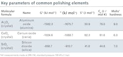
Particle size (d50) and size distribution were concerns, since the dangers of using materials with broad distribution were well understood. All slurries were premixed and tumbled to break down the larger particles and homogenize particle size, which evenly distributes particle loading and minimizes high localized pressure on the glass that leads to fractures (see Fig. 1).
Incoming substrate material was carefully controlled to ensure quality and accuracy of results. Corning 7980 was used exclusively, and due to the slow nature of the diffusion process and low penetration depth, surface quality and maximum average roughness (Ra) were specified to 10-5 and 5 Å, respectively. Planar surfaces were created on a continuous polisher having two work rings and a conditioner.
A set of planar fused silica surfaces were examined using atomic force microscopy (see Fig. 2). One surface was produced with traditional grind and polish techniques that produced average and peak-to-valley (P-V) roughness values of 1.55 Å and 29.6 Å, respectively. Even with a high-quality polish, surface structure is still apparent, as the polishing particles rip through the Beilby layer to fracture the substrate. This condition is understandable, given that an average polishing particle of 500 nm cuts right through a Beilby layer of 6 nm to damage the substrate.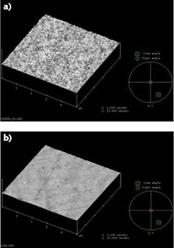
The other surface was produced with the Edmund Optics (EO) process focused on repeated removal of only the Beilby layer. It has average and P-V roughness of 1.07 Å and 3.71 Å, respectively, and lacks any visible surface structure. The average size of ceria particles can range from several Angstroms to several nanometers and, as such, can easily lodge within the structure of the 29 Å surface and be difficult to remove, even with ultrasonic cleaning. Since ceria is known to absorb at many laser wavelengths, these surface particles can contribute to lower laser damage threshold (LDT) levels.
Look at both P-V and average roughness values
Metrology should consider both P-V and average values to provide a complete description of the surface, as well-controlled, consistent surfaces will possess similar P-V and average roughness values (see Fig. 3). All metrology done with the Zygo NewView profilometer was performed using a 20X Mirau objective, 1X Zoom, BPF, FFT Fixed, 9–250 mm-1, 10X average, System Error removed. More than 500 samples were processed of EO P/N 37689, Corning 7980, 25.4 mm diameter and 6.35 mm thick, with over 99% yield.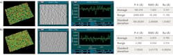

The fact that N-BK7 material achieved sub-Angstrom roughness with a process designed for fused silica was due in part to the:
- Solubility of borates, which is higher than silicates and allows them to be affected by the water-based slurry through a loosening of their bond with the substrate.
- Smaller size and lower strength of the boron-oxygen molecule, which was removed along with the silicon-oxygen-ceria compounds.
The higher roughness of N-BK7 material is attributed to the combined effect of several elements found in borosilicate glass such as B2O3, SiO2, Na2O, and Al2O3.
Polishing of silicon required a different chemistry due to the crystal structure and absence of silicate glass compounds (see Fig. 5). However, application of the basic principles of particle separation, correct pressure, and chemistry yielded excellent results. Substrate material was EO P/N 68527, optical-grade silicon, 25 mm diameter and 3 mm thick. The surface of the incoming silicon had been degraded from stock conditions due to previous experimentation.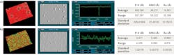
Polishing of calcium fluoride (CaF2) also required a change in chemistry that differed from both the glass and silicon compositions. Substrate material was EO P/N 47683, vacuum-UV-grade CaF2, 25 mm diameter and 3 mm thick. The surface of the incoming CaF2 had been degraded from original conditions due to previous experimentation.
While Ce3+ is soluble in water, Ce3+ can combine with F- ions to form CeF3, which is insoluble, very hard, and will precipitate on the CaF2 surface to form a substance that is difficult to remove.9 At the other end of the pH scale, CO2 from the air will react with water to form carbonic acid, which may then form carbonate ions. This substance is also very difficult to remove from surfaces, so pH must be maintained within reasonable limits to inhibit formation of these compounds. Figure 6 reflects CeF3 precipitates on the crystal surface that were removed via processing at EO.
Sub-Angstrom surfaces have been demonstrated and consistently produced on fused silica, borosilicates, silicon, and calcium fluoride windows. More than 600 surfaces have been produced with these methods at a yield of over 99%. Surfaces produced by this method revealed no surface structure and no detectable subsurface damage.
REFERENCES
1. L. M. Cook, J. Non-Cryst. Solids, 120, 1–3, 152–171 (Apr. 1, 1990).
2. T. Suratwala et al., J. Non-Cryst. Solids, 352, 52, 5601–5617 (Dec. 2006).
3. See https://bit.ly/ChemMechPol.
4. M. J. Cumbo, D. Fairhurst, S. D. Jacobs, and B. E. Puchebner, Appl. Opt., 34, 19, 3743–3755 (1995).
5. Sir George Thomas Beilby, Aggregation and Flow of Solids (1921).
6. M. Nogami and M. Tomozawa, J. Am. Chem. Soc., 67, 2, 151–154 (Feb. 1984).
7. W. A. Lanford, C. Burman, and R. H. Doremus, Advances in Materials Characterization II, 19, 203, Springer US (1985).
8. J. Nelson and S. Iles, Proc. SPIE, 11175, 1117505 (Nov. 15, 2019); doi:10.1117/12.2536689.
9. R. Khatib et al., Sci. Rep., 6, 24287 (2016); doi:10.1038/srep24287.
About the Author
Shawn Iles
Optical Manufacturing Engineer, Edmund Optics
Shawn Iles is Optical Manufacturing Engineer at Edmund Optics (Tucson, AZ).
Jayson Nelson
Manufacturing Technology Manager, Edmund Optics
Jayson Nelson is Manufacturing Technology Manager at Edmund Optics (Tucson, AZ).