Virtual prototyping before hardware: From optical design to system performance
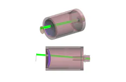
An optical design can meet its specifications and still fail at the system level. Consider an imaging instrument’s output being interpreted by an algorithm rather than viewed directly by a person. Image quality alone does not determine whether the system can detect, classify, or measure what matters. Virtual prototyping brings the operating environment, optics, detector, and processing chain into one model before hardware exists. Engineers can then evaluate the result the system must deliver—not only the performance of its optical components.
Optical validation can’t wait for hardware
Optics play an increasingly important role in digital systems that act on sensed information. Examples include a spaceborne optical sensor mapping the Earth or a vehicle’s advanced driver-assistance system (ADAS) that decides which of its camera sensors to trust and act upon. In these cases, the optics supply information that downstream electronics and software must interpret. Component-level validation can only show the component meets a specific optical specification rather than that the complete system will accomplish its intended task.
This is important because feedback between optical design, fabrication, and system integration is neither fast nor inexpensive. A mismatch between the optical specification and the required system performance may not appear until lenses have been fabricated, coated, assembled, and integrated. Photonic integrated circuits pose a similar challenge because another fabrication cycle can create project delays. Custom optical components and assemblies generally can’t be replaced and retested in one afternoon. Effective development shifts validation ahead of fabrication and uses simulation at both the component and system levels, including all relevant environmental effects.
Simulation is mandatory
Virtual prototyping goes further than modeling just the optics. It simulates the entire signal chain: Illumination interacting with the scene, light propagating through the optical train and the detector, and processing that turns a signal into a result. A digital twin underpins this with a model built on modeled and measured component behavior rather than ideal assumptions, so the detector, coatings, and materials behave in simulation as they do on the bench. Optical simulation verifies the optical design meets its specification, but it does not evaluate whether the other parts of the system or the complete system can do its job.
For an imaging example, the virtual prototype produces a simulated image of what the instrument sees that includes how illumination interacts with the object, how the optics image the incoming light, what the effect of stray light is, as well as the detector's modulation transfer function (MTF), quantum efficiency, and noise characteristics.
Processing algorithms can then be tested and refined on this data, so image processing teams can iterate months before any hardware exists. By the time the first unit is built, both the optics and the algorithms should already be near their final form. Evaluating the full signal chain in simulation exposes system-level problems earlier, while waiting for a physical product to test often means problems surface too late and are expensive to fix.
Modeling light the instrument will encounter
A simulation is only as useful as the conditions it is given. A model built on ideal assumptions can often confirm a design the real world breaks. Closing this gap takes more than meeting the imaging specifications for the optics. The environment must also be included in the simulation. It means modeling the real-world conditions the imager will encounter in use, such as the sun sitting just beyond the field of view, entering the aperture, scattering off internal surfaces, and reaching the detector as stray light. Ghost reflections, diffraction from apertures, and, for infrared systems, the lens assembly’s own thermal emission can all contribute.
A digital twin evaluates these conditions against the design. The optical prescription alone can’t predict stray light, and the result depends on what surrounds the instrument and how it interacts with what’s inside it. The design is made for a particular imaging condition and engineers can test it with the stray light present within the environment and then make modifications. It might involve moving geometry, adding baffles, painting surfaces, or changing coatings.
Consider an Earth observation instrument that must produce high-resolution imagery, hold radiometric accuracy, and maintain that at every solar angle and surface it flies over. Each representative case must be analyzed and mitigated during the design phase. Running this loop in hardware means rebuilding and retesting for every situation and waiting to see how it performs in space. This feedback would be too late. In a model, this loop can be accomplished with a parameter change, so the problem is not confined to space. A vehicle may carry six or even more imagers, and the system-level question is not whether one of them handles stray light but which one is returning usable data at a given moment. It depends on where the sun sits, streetlights and headlamps, and what the surrounding surfaces reflect, and each varies independently. No single imager fails. The system degrades because the combination falls outside what it was qualified against. Waiting for this combination to show up is not a test plan.
From optical performance to system performance
Environmental conditions present a similar problem because temperature variations and thermal gradients change how an instrument performs, and qualifying for them requires having the hardware in hand. This validation is mandatory, particularly for space, where thermal vacuum testing is standard because it can confirm performance but issues should be discovered in simulation. Finite element analysis (FEA) addresses something ray tracing alone can’t: How the structure performs under thermal load. The deformed geometry then goes into the optical model, so performance is computed for the shape the system takes at temperature, not the nominal condition it was designed to hold. FEA is an input to the virtual prototype, not a stage before it. Together, they still stop at the optics.
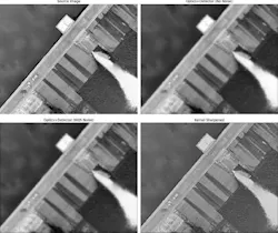
System performance is a different question and the detector sits between the two, sampling the image and converting a fraction of the photons reaching it. A design can meet its specification but produce an unsuitable result. Running the full chain identifies where a problem is best fixed while there’s time to act. Barrel distortion that pushes corner features out of shape can be corrected in image processing instead of in glass, where the fix means a larger and more expensive lens. The model shows what this choice costs before the lens is committed.
Software-defined engineering
Workflows depend on analyses easily integrated across tools, and the reach of these models is growing because the tool chain is changing. System-level analysis, component design, and photonic integrated circuit layout have occupied separate environments with separate models. A connected tool chain allows engineers to begin with system requirements, move to the subsystem and component design details, and run performance analysis without rebuilding at each step.
Software needs are evolving too, while traditional optical tools assume an engineer is operating a graphical interface. Many customers want an AI design agent supplied with the tools. Some organizations are going further and building their own agents, which require well-documented application programming interfaces (APIs) and model context protocol (MCP) servers a machine can reliably drive. Machine-driven workflows place new demands on software architecture. Engineers are adaptable and can create implicit models of how things work on the fly. If an engineer encounters an undocumented quirk, they can work around it and move on. An agent thrives on explicit, modular, and discoverable structure, so the tool must be designed to accommodate it.
Validation moves earlier
Optical engineering has always been constrained by how late critical answers arrive. Fabrication lead times remain long, but virtual prototyping moves system-level decisions earlier. Engineers can explore performance, environmental effects, and design tradeoffs, and then use hardware to confirm the result.
About the Author
Paul Townley-Smith
Paul Townley-Smith is Keysight Technologies’ principal program manager and has spent 35 years managing fast-paced programs and making cutting-edge optical devices across a broad range of applications, including optical telecom, Earth-observing telescopes, head-mounted displays, medical products, lithography, and defense. He has helped multiple startups reach their exit goals.