Ultrafast Laser Machining: High-rate laser microprocessing handles large-area substrates
High-rate laser microprocessing is becoming a key enabling technology for modern microfabrication and production. Recent high-rate machining technology combines the advantages of high-power lasers and high-speed processing. The primary goal is to bring innovative and well-established laser micromachining processes from the lab to the industry to enhance productivity, processing speed, and throughput. This becomes possible, on the one hand, by recent progress in the development of laser sources supplying hundreds to thousands of watts of laser power with excellent beam quality, as well as high-average-power ultrafast lasers. Ultrafast scan systems, another core feature for high-rate machining, can avoid thermal damage to the substrates, even at high laser powers, by deflecting the laser beams at unprecedented speeds.
In one promising approach, large-aperture polygon-mirror-based scan systems are combined with long-focal-length objectives to enable rapid beam-spot motions ranging between several tens of meters to kilometers per second. Thanks to the excellent beam quality, small spot sizes of several 10 µm can be delivered over large scan fields up to 700 × 700 mm2. For precision microprocessing, laser activity is controlled by fast laser beam switching to precisely synchronize the laser beam with the ultrafast polygon scan system.
Large-area microscale features
High-rate laser micromachining is well suited for producing microscale surface features with structural dimensions ranging from hundreds of nanometers to several tens of micrometers. Inspired by nature, these (sub)microscale features can be used to control mechanical, chemical, and physical surface functionalities including, for example, self-cleaning and wettability, static friction and adhesion, optical and microfluidic properties, and so on.
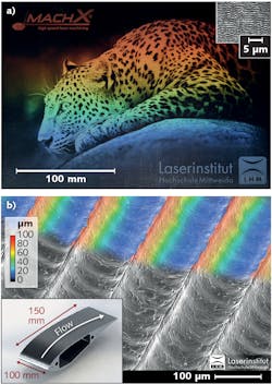
One example shows a large-area ripple-textured AISI 304 surface processed with a high-average-power femtosecond laser (1030 nm, 400 fs, 450 W) using the polygon scan system (see Fig. 1a). With a 500 m/s scan speed, the processing rate for this 280 × 190 mm2 diffraction grating was 2000 cm2/min. Inspired by the riblet effect known from shark skin, Figure 1b shows a laser-textured drag-reducing surface topology on an aluminum airfoil, processed using a continuous-wave (CW) single-mode fiber laser with a power of 2.7 kW and a scan speed of 150 m/s—the processing rate was 0.82 m2/h.
The example machined pieces were generated by a polygon mirror scanner, which can be purchased by MOEWE Optical Solutions. This scanner has a large free aperture of 31 mm, achieved by the use of a novel distortion-free double polygon mirror. The design allows for a compact design for the 2D scanner despite the large aperture. The polygon scanner is fully digitized: using an integrated field-programmable gate array (FPGA) with a frequency of 200 MHz, the scanner is geometrically optimally corrected and it can react in real time to external influences such as axis movement.
Conventional f-theta optics can be used with the scanner. An f-theta optic with a focal length of 420 mm is installed in the system, producing a focal spot of approximately 40 µm. The processing area in this case is approx. 300 × 300 mm2. By using the external axis, a line width of 400 mm can be processed. The maximum scanning speed and line frequency are 1000 m/s and 1.3 kHz, respectively. For this purpose, the polygon mirror rotates at 11,000 rpm. A full correction of the scan field (line tilting, pincushion distortion of f-theta optics) by the integrated digital electronics is possible up to a speed of 200 m/s.
A mainly parallel working FPGA logic with a cycle time of 5 ns is used within the scanner, and two 600 MHz processors serve as the communication. To satisfy high-speed microprocessing demands, a large amount of data needs to be processed during each scan line of the polygon (polygon line = fast axis). At maximum speed, more than 80 MB/s of data must be processed. Due to the additional requirement of having instantaneous data output at specific scan positions (a real-time system), dynamic transfer is not possible. Therefore, the polygon scanner itself contains 1 GB of DDR RAM with a maximum data rate of 800 MB per second.
The scanner can work in three different operation modes. In the bitmap mode, an up to 32-bit gray-encoded bitmap represents the laser power that is to be applied at each scan position. In depth-map mode, the stored bitmap contains the depth information for each scan position. Via multiple-cycle irradiation of the whole scan field, a 2.5D engraving (the creation of multiple flat features at varying depths) can be performed. In vector mode, a surface tessellation language (STL) file is loaded into the memory and the polygon scanner performs a real-time slicing of the 3D data as necessary for selective laser sintering. For all three modes of operation, fast switching of high-power lasers must apply. At present, the scanner has been tested with CW laser sources up to 3 kW, nanosecond pulsed systems with peak power up to 10 kW, and ultrashort-pulsed systems. Upcoming tests will be done with a 10 kW single-mode CW fiber laser system.
Modular laser platform
To take advantage of the potential of the polygon scanner system and the full power of the laser source for industrial applications, it is necessary to integrate the equipment into a reliable micromachining system. For this purpose, 3D-Micromac provides a modular laser platform, called microSHAPE, to bring all those requirements together. The laser system is designed for high accuracy and high dynamic processing of large and flat glass and metal substrates. The scalable design can address sheet sizes up to 2 × 3 m. Software controls all components and aligns the laser source, the polygon scanner, and the overall beam path.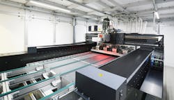
The microSHAPE is based on a gantry design that can be specially configured in dynamics, metrology, handling, and laser and beam-delivery components. Depending on its configuration, an axis accuracy of ±2 μm, a process accuracy of ±10 μm, and processing speeds of up to 1.5 m/sec are possible. The microSHAPE system is widely used in industrial production. In addition to configurations including a polygon scanner for surface modification of stainless-steel substrates (see Fig. 2), the system is used for all sorts of ablative and nonablative cutting or structuring processes, such as glass filamentation (cutting glass with ultrafast lasers).
ACKNOWLEDGEMENT
The presented results have been conducted in the course of the projects ”Optimierung der stroemungsmechanischen Auslegung von Energiemaschinen durch Einsatz von Hochrate-Laserstrukturierungstechnologien - OstrALas” (03PSIPT1A) and “Erweiterung der Infrastruktur für den Ausbau des spezifischen Forschungs- und Innovationsprofils “Hochrate-Laserbearbeitung - Hochrate2.0” (03IPT506I), funded by the Federal Ministry of Education and Research.
About the Author
André Streek
Professor of Laser Technology, Laser Institute of Mittweida
André Streek is professor of laser technology at the Laser Institute of Mittweida (Mittweida, Germany).
René Liebers
Technology Manager, 3D-Micromac
René Liebers is technology manager at 3D-Micromac (Chemnitz, Germany).
Udo Loeschner
Professor of Laser Manufacturing Technology, Laser Institute of Mittweida
Udo Loeschner is Professor of Laser Manufacturing Technology at the Laser Institute of Mittweida (Mittweida, Germany).