Laser Beam Quality: Beam propagation and quality factors: A primer
Characterizing a laser system may seem like a daunting task, especially when just the laser source itself has many influencing factors, such as power stability, coherence, and wavelength, that govern which application it is most suitable for. However, there are a few key parameters concerning the beam profile itself that provide some insight into the overall system performance, whether it is a Gaussian beam in metrology, or the higher-order modes often produced by a diode laser system or by high-power materials-processing lasers.
In a single plane perpendicular to the propagation axis, a laser beam has a beam width, a radius, and a spatial intensity distribution. From the near field to the far field, each of these values will change. How much they change will affect the brightness of the beam and its ability to be focused to a spot.
This article will discuss beam propagation and quality factors, including the beam quality (M2) factor, beam parameter product (BPP), power in the bucket (PIB), and Strehl ratio, as well as which laser systems they are most suited for. Each beam-quality metric has its advantages and disadvantages, and as a result the correct metric for an individual use case is highly application-dependent. The ISO 11146 standard will be referenced here, as it provides an excellent starting place for definitions and test methods covering laser beam propagation.
M2 factor
For laser beams for which the second-order moments of intensity (beam width) and divergence can be determined, the beam-propagation ratio M2 is often used to characterize beam quality. The M2 factor compares the actual shape of the beam to that of an ideal Gaussian beam.
The ISO Standard 111461 defines the M2 factor as:
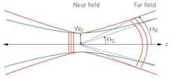
1.In Equation 1, w0 is the beam waist, θ is the divergence angle of the laser, and λ is the lasing wavelength (see Fig. 1).
The divergence angle of a Gaussian beam is determined by Equation 2:
2.The resulting divergence angle can be inserted into Equation 2 to simplify the calculation of the M2 factor of a Gaussian beam:
3.An M2 factor of 1 corresponds to a diffraction-limited Gaussian beam, and M2 factors larger than 1 correspond to a beam that deviates from the ideal Gaussian beam. It is impossible to achieve a value less than 1. Helium-neon gas lasers typically have an M2 factor somewhere between 1 and 1.1.
It is important to know the M2 factor of a laser beam for any application in which it is focused to a spot. For a given divergence angle, the M2 factor can be a measure of how effectively the beam can be focused. The lower the M2 factor, the tighter the focus and the more intense a beam spot can be achieved.
The Rayleigh range can also be shown to decrease with increasing M2 factor:
4.Measuring M2 is more involved than simply taking a measurement of the beam profile at a single plane along the propagation axis. According to the ISO 11146 standard, five separate beam-radius measurements must be recorded at various positions in both the near field and the far field along the propagation axis. The test equipment for the measurement, which may include a camera, moving pinhole, moving knife edge, moving slit, and/or variable aperture, is dependent on the beam itself, and ISO 11146 should be referenced for the best method to be used.
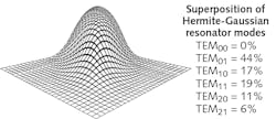
Even though the cross-section at a specific plane may look like a perfect Gaussian distribution, the beam may propagate very differently than a Gaussian beam and in that case will have a greater divergence angle. Figure 2 shows why multiple radius measurements at different planes are needed to calculate M2.One disadvantage of this metric is that it weighs the contributions from the “wings” (the low-power-density regions further away from the center of the beam) more than other methods, occasionally making the M2 factor more useful in academic settings than industrial applications. Described below are a couple of other methods that can provide additional information about the beam quality and its propagation characteristics.
Beam-parameter product
The beam-parameter product (BPP) is another parameter often used to characterize the quality of a laser beam. According to the ISO 11146 standard, the BPP is given by the product of the beam radius (measured at the beam waist) and the half-angle beam divergence (measured in the far field). BPP is typically reported in units of mm-mrad, and it can be related to the M2 factor by:
5.Because the M2 factor is directly proportional to the BPP, a larger BPP indicates a beam of worse quality that is less similar to an ideal Gaussian beam. The minimum achievable BPP value is λ/π, which corresponds to an ideal Gaussian beam. For example, the minimum possible BPP of a beam with a 1064 nm wavelength is about 0.339 mm-mrad.
BPP is often used for multimode semiconductor or fiber lasers with large M2 factors. Typical BPP values for high-power commercial products are 3 to 10 mm-rad.2 Engineers looking for a simplified calculation to evaluate diode-laser fiber-coupled designs often look to BPP to help determine the amount of light that can be coupled into the fiber.3
Power in the bucket
Power in the bucket (PIB) is another parameter used for describing beam propagation and quality, and is commonly used in materials-processing and other high-power laser applications, as PIB has a direct bearing on the ability to form a small and intense spot on an object or a material being processed.
PIB refers to the fraction of total power that can be delivered into a cone, measured in angular units λ/D and called a “bucket,” where λ is the laser wavelength and D is a characteristic size of the initial beam. While there is no industry standard for defining and measuring PIB, the High Energy Laser Joint Tech office uses a two hard aperture geometry for PIB measurement, as shown in Figure 3.4A lower PIB value corresponds with a higher-quality beam, just as for the M2 factor and BPP.
A laser beam’s vertical beam quality5 is given by the square root of the ratio of the fraction of power in the bucket of a perfect Gaussian beam. This ratio is unique for a given λ/D. The vertical beam quality corresponds to the plot’s vertical dimension and is most meaningful when the beam is nearly diffraction-limited.
6.The beam’s horizontal beam quality is given by the ratio of the λ/D value of a perfect Gaussian beam to that of the real beam at a given fraction of power in the bucket. This corresponds to the horizontal dimension of the plot and is useful when the beam is significantly worse than diffraction-limited.
7.PIB curves, such as in Figure 4, clearly display the amount of total beam power contained in the central beam lobe and what fraction of the beam is distributed in a weak but large area extending outside of the main portion of the beam. This can be more informative and useful than a complete beam-intensity profile.
Simply measuring several points along a PIB curve gives a substantially improved understanding of a laser beam’s quality of a laser beam.6
Strehl ratio
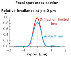
Similarly to how the M2 factor allows the performance of a real laser to be compared to that of an ideal beam, the Strehl ratio of an optical system or component allows the optics’ true performance to be compared with that of an ideal version. Historically used in the astronomy community thanks to the work of Karl Strehl in 1894 and revisited by Virendra Mahajan in 1983,7 the Strehl ratio of an optic is approximately related to its root-mean-squared (RMS) transmitted wavefront error by Equation 8, where S is the optic’s Strehl ratio and σ is the optic’s RMS wavefront error in waves. This equation is valid for RMS wavefront error values less than or equal to λ/5.
8.Strehl Ratio is also dependent on the f-number of the lens. In general, faster lenses, or lenses with small f-numbers, are more sensitive to wavefront error and thus can lead to more performance degradation.
For a Gaussian or aberrated-Gaussian beam,8 we can define the Strehl equivalent M2 for the wavefront error of the lens or mirror as:9
9.For systems where thermal distortion is not a concern, the M2 factors for the laser and the optics can be combined to produce an M2 factor for the total system.
10.
One takeaway from this is that for high-power lasers with poor M2 values, the effort to implement diffraction-limited optics is less critical, as small amounts of lens wavefront error will not significantly affect the beam divergence and image size.
Whether you are designing a laser system for fluorescence microscopy, materials processing, or rangefinding, it is important to understand your beam at the source and at the target. The factors and ratios described herein will help you on your way to an improved understanding of your overall laser system performance.
REFERENCES
1. “ISO 11146 Lasers and laser-related equipment – Test Methods for laser beam widths, divergence angles and beam propagation ratios,” ISO (2005).
2. K. J. Kasunic, “Laser Systems Engineering,” SPIE, Bellingham, WA (2016).
3. Z. Wang, “Fiber coupled diode laser beam parameter product calculation and rules for optimized design,” Proc. SPIE, 7918, 9 (2011).
4. J. Slater, “A Beam Quality Metric for High Energy Lasers,” High Energy Laser Joint Technology Office (2016).
5. K. W. Strehl, “Theory of the Telescope Due to the Diffraction of Light,” Leipzig (1894).
6. A. E. Siegman, “How to (maybe) measure laser beam quality,” OSA TOPS, 17, Diode Pumped Solid State Lasers, OSA (1997).
7. V. N. Mahajan, J. Opt. Soc. Am. A, 73, 6 (1983).
8. T. S. Ross, “Laser Beam Quality Metrics,” SPIE Press, Bellingham, WA (2013).
9. G. Golnik, “The Infrared and Electro-Optical Handbook Vol. 8,” SPIE Press, Bellingham, WA (1993).
About the Author
Randall Hinton
Senior Solution Engineer, Edmund Optics
Randall Hinton is a senior solution engineer at Edmund Optics (Barrington, NJ).


