Laser Coherence: Spatial coherence engineering of lasers enhances use for illumination
HUI CAO
Lasers have enabled major scientific and technological advances due to their high brightness, high coherence, high efficiency, and good spectral control. However, high spatial coherence can cause deleterious effects such as speckle noise, limiting laser application in full-field imaging, parallel projection and display, materials processing, optical trapping, holography, and lithography.
To avoid speckle, lamps and LEDs of low coherence are often used as illumination sources. These sources have low power per mode, which is insufficient for imaging through a scattering medium or for high-speed imaging with short recording time. Alternatively, lasers can be used in a raster-scanning mode—however, scanning is time-consuming and not suitable for imaging of moving objects or transient processes. Parallel imaging is desirable because of high speed, but it requires an illumination source with high power and low coherence.
A common way of reducing the spatial coherence of a laser is to generate many speckle patterns with a time-varying scattering system and then sum the intensities. Even though each speckle pattern has a contrast of unity, an incoherent sum of N uncorrelated speckle patterns reduces the speckle contrast by a factor of N1/2. Lowering the speckle contrast to below the level of human perception (<3%) requires summing about 1000 different speckle patterns. The imaging speed is then limited by the time it takes to sequentially generate these speckle patterns.
Instead of first making a highly coherent laser only to then reduce the spatial coherence of its emission with a spinning diffuser, why not just insert the diffuser into the laser cavity to reduce spatial coherence directly? Since the diffuser scatters light, the question is whether lasing can still be achieved with scatterers inside the cavity. The answer is yes. In fact, the more scatterers, the lower the lasing threshold.
Random lasing
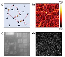
When a gain medium consists of many scatterers, the spontaneously emitted photons will be scattered multiple times and undergo a “random walk.” The increase in the path length of photons in the gain medium enhances light amplification via stimulated emission of photons (see Fig. 1a). Furthermore, the scattered waves may return to spatial positions that they have visited before, providing feedback for lasing oscillation. Thus, lasing can occur without a conventional cavity; such a laser is called a random laser.1
Random lasers can operate in a highly multimode regime. Individual lasing modes, formed by interference of scattered waves, have distinct frequencies and spatial structures (see Fig. 1b). When a large number of modes lase simultaneously with uncorrelated phases, their distinctly speckled wavefronts combine incoherently to produce emission with low spatial coherence.2, 3 Because the reduction of spatial coherence does not rely on the motion of scatterers inside the cavity but on multimode lasing, the scatterers may be static. The time it takes for spatial coherence reduction is given by the spectral linewidth and frequency spacing of individual modes. Speckle-free full-field imaging is demonstrated with random laser illumination in the setting of intense optical scattering (see Figs. 1c and d).4
Compared to lamps and LEDs, the random laser emission is much stronger and allows much shorter exposure time and much higher speed for full-field imaging of transient processes.5, 6 For example, a random laser can be triggered to produce a short illumination flash at a well-defined delay time, enabling time-resolved speckle-free wide-field microscopy with an exposure time as short as 10 ns.
Studies of random lasers reveal how to design a laser with low spatial coherence. First, the laser cavity must support numerous low-loss modes of similar quality (Q) factor, so that they have a similar lasing threshold. Secondly, mode competition for gain must be minimized so that many modes can lase simultaneously. Finally, these modes should have distinct emission patterns so that, when they lase independently, an incoherent sum of their emission intensities lowers the spatial coherence. Of course, combining mutually incoherent emission from many uncoupled lasers, such as a vertical-cavity surface-emitting laser (VCSEL) array, can lower the spatial coherence. However, incorporating all lasers to a single cavity will reduce the system size and fabrication cost, as demonstrated by the wave-chaotic microcavity laser.
Wave-chaotic cavities feature chaotic ray dynamics, in contrast to regular ray dynamics in conventional laser cavities. One example is the D-shaped cavity: a two-dimensional (2D) circular cavity with a section removed along a straight cut (see Fig. 2a). This cut eliminates the whispering-gallery modes that have extremely high Q factors. The remaining modes have a pseudorandom structure (see Fig. 2b). They have similar Q factors and, hence, lase with almost identical thresholds. Because their spatial profiles are spread over the entire cavity, their competition for gain is reduced as compared to whispering gallery modes that are concentrated near the boundary of a circular cavity. Consequently, more than 1000 modes lase simultaneously and independently in a D-shaped gallium arsenide (GaAs) disk with a radius R of 500 µm, producing emission of low spatial coherence.7 The disk is fabricated on a commercial GaAs quantum-well wafer via standard photolithography and wet chemical etching. Lasing is achieved at room temperature with electric current injection. The spectral radiance of the D-cavity laser, measured by photon degeneracy number δ (the number of photons per coherence volume), is 4–5 orders of magnitude higher than that of a thermal source or of a bright LED. For speckle-free imaging, the D-cavity laser is the brightest illumination source available, with a compact size and low cost.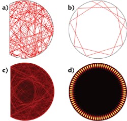
Spatial coherence gating for microscopy
In addition to high-speed, speckle-free full-field imaging, a source with low spatial coherence and high power per mode enables massively parallel phase-sensitive interferometric confocal microscopy. It was shown that spatial coherence gating provides 18,000 continuous virtual pinholes for imaging the entire en face plane in a snapshot.8 The integration time is as short as 100 μs and the 2D frame rates exceed 1 kHz. The interferometric detection retrieves both amplitude and phase of optical signals. An ultrahigh-speed, phase-sensitive, full-field reflection interferometric confocal microscope (FFICM) was developed for in vivo quantitative microscale physiology—for example, visualization and quantification of cilia-driven surface flows and cilia beat frequency in tadpoles.9 The lateral resolution is 2 μm and the axial gating depth is 8 μm.
Although speckle poses a serious issue for imaging the structure of an object, its temporal fluctuation caries useful information about the motion of the object. Laser-speckle contrast imaging relies on time-varying speckle created by moving blood cells to map blood flow in living tissue. To obtain both anatomical and functional information on living tissue, speckle-free and speckled images are recorded with two separate illumination sources: a laser and a LED. However, a single illumination source with tunable spatial coherence but constant power will eliminate additional optical alignment and potential power change. To this end, an efficient method of tuning the spatial coherence of a degenerate laser was developed.10
A degenerate cavity is a self-imaging system, as exemplified in Figure 3a, that shows two lenses in a 2f1–2f2 telescope arrangement between two flat mirrors. Because an arbitrary field distribution at any plane in the cavity is imaged onto itself after one round trip, any field distribution is an eigenmode of the cavity. All eigenmodes are degenerate, having identical lasing threshold. In a degenerate solid-state laser, more than 105 transverse modes lase simultaneously and independently, producing emission with extremely low spatial coherence.10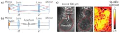
To tune the degree of spatial coherence, the number of transverse lasing modes is varied by inserting a variable circular aperture to the mutual focal plane of the two lenses, as shown in Fig. 3b. The aperture serves as a spatial filter that introduces loss to high-order transverse modes. When the aperture is sufficiently small, only the lowest-order transverse mode lases. Because the spatial overlap between the lasing mode and the gain medium remains the same, the total power extracted from the gain medium is unchanged.
Experimentally, decreasing the diameter of a circular aperture in a solid-state degenerate cavity changes the number of transverse lasing modes from 105 to 1, while the output power reduces by less than 50%. The spatial-coherence properties can be further engineered by resorting to more sophisticated intracavity spatial masks. For example, a variable slit enables independent control of the degree of spatial coherence in one coordinate axis without affecting that in the orthogonal axis.11
Both structural and functional information are obtained
The spatial coherence of an electrically-pumped semiconductor-based degenerate vertical external-cavity surface-emitting laser (VECSEL) was switched for imaging the embryo heart function in Xenopus, an important animal model of heart disease (see Fig. 3c).12 The low-spatial-coherence illumination was used for high-speed (100 frames per second) speckle-free imaging of the dynamic heart structure, and the high spatial-coherence illumination for laser speckle contrast imaging of the blood flow. Therefore, a single source can be employed for two microscopy modalities to obtain both structural and functional information.
Spatial-coherence control of lasers not only provides an efficient means for eliminating coherent artifacts, but also enables new applications. These schemes for reducing and switching the spatial coherence are applicable to a variety of lasers that operate at different wavelengths and with different gain materials. Each scheme has its own advantages and is suitable for different applications.
REFERENCES
1. H. Cao, Optics and Photonics News, 16, 24–29 (2005).
2. B. Redding, M. A. Choma, and H. Cao, Opt. Lett., 36, 3404–3406 (2011).
3. B. H. Hokr et al., J. Mod. Opt., 63, 46–49 (2016).
4. B. Redding, M. A. Choma, and H. Cao, Nat. Photonics, 6, 355–359 (2012).
5. A. Mermillod-Blondin, H. Mentzel, and A. Rosenfeld, Opt. Lett., 38, 4112–4115 (2013).
6. B. H. Hokr et al., Sci. Rep.-UK, 7 (2017).
7. B. Redding et al., Proc. Nat. Acad. Sci. USA, 112, 1304–1309 (2015).
8. B. Redding et al., Opt. Lett., 39, 4446–4449 (2014).
9. I. Sencan et al., Biomed. Opt. Express, 7, 4674–4684 (2016).
10. M. Nixon et al., Opt. Lett., 38, 3858–3861 (2013).
11. R. Chriki et al., Opt. Express, 23, 12989–12997 (2015).
12. S. Knitter et al., Optica, 3, 403–406 (2016).
Hui Cao is the John C. Malone Professor of Applied Physics and of Physics at Yale University, New Haven, CT; e-mail: [email protected]; https://appliedphysics.yale.edu/hui-cao.