High-performance tools position accurately
Positioning equipment can be used to align laser beams and optical elements, assemble and inspect devices, and manipulate industrial processes and procedures. The equipment includes stages, motors, actuators, and controllers, which encompass all of the electronics necessary to make a laser system move. Manufacturers offer the equipment at the component level as well as at integrated-system and subsystem levels.
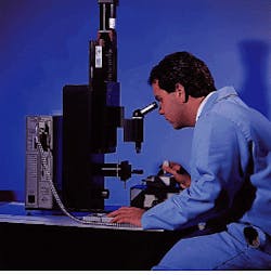
Demanding requirements in several key application areas have been driving performance improvements in positioning equipment. Finer resolution, better repeatability, higher levels of precision and accuracy, and longer mean time between failure (MTBF) are just a few of the specifications of concern to engineers and scientists working in the semiconductor, biomedical, electronics, and robotics industries (see Fig. 1). Such improved specifications are required in both research and industrial applications; they differ primarily in the level of robustness and automation required. Factors influencing a positioning-equipment purchasing decision include performance issues, ease of use, durability, ease of systems integration, and, of course, cost. Pre- and postsales support are also highly rated.
This Product Focus briefly describes some of the components found in a typical positioning system and some of the current systems-integration issues. Several interesting applications and their positioning demands are reviewed. For a comprehensive listing of manufacturers and suppliers, please see the positioning-equipment section that begins on p. 630 of the 1997 Laser Focus World Buyers Guide. This article does not cover nanometer positioning using piezoelectric positioning (see Laser Focus World, Nov. 1996, p. 161) or fiberoptic positioning componenets (see Laser Focus World, Feb. 1996, p. 137).
The positioning-equipment market is dynamic--prospective purchasers should contact manufacturers for further information about the latest available products. Many vendors, in their catalogs and product literature, provide detailed discussions on the theory and implementation of their sub systems, as well as product-level information on components.
Stages, motors, and actuators
Motion-control systems are generally constructed of several common components. A stage is the platform upon which rests the object to be moved. Stages accommodate either linear or rotary motion; the drive or actuator mechanism can be a ball screw or a lead screw and can be belt-driven or have an air bearing. Stages also come in several versions: dovetail slides, ball-bearing slides, crossed-roller bearings, and flexure stages. The different stages and drives provide different levels of precision, speed of movement, repeatability, and robustness. Length of travel and the weight of the object to be moved are important factors in sizing a system and may rule in or out various systems. It is also important to know whether the position of the stage during the motion matters or if its location at either end is the only critical factor.
Motion-control systems can work manually. A high-quality micrometer is an extremely accurate device for adjusting a stage using a screw drive. However, most industrial motion systems and even many laboratory systems are motorized, enabling process automation. There are several choices among motors, some of which are dictated by the selection of the type of stage. These drivers amplify the signal received from the system`s electronics to provide needed forces to operate the system. Microstepping and stepping drives, dc brush or brushless servo drives, and linear brushless motors are all available. The choice among the motor drivers depends upon the requirements of the application for repeatability, resolution, speed, and remote control. Position verification is usually accomplished by means of an encoder. The highest level of encoder performance has the device measuring the final position of the stage rather than the movement or position of the drive train.
System electronics
While there have been important improvements for the mechanical elements in precision and resolution, the electronics are proving to be the area of challenge and interest in current system design. Two basic components comprise the electronics portion of a system—the motor driver and the controller, sometimes called an indexer. A controller provides the intelligence of the system, calculating trajectories and motions, remembering encoder pulses, sending signals to the motor and driver, and communicating with the host computer or other external device. Configurations vary—one controller can send signals to multiple motors or there can be a dedicated controller for each motor driver. The driver can be integrated with the controller or the controller can be integrated within the host computer, in which case the driver and motor are remote.
Many users are concerned about interfacing a positioning system with their host computers and with other subsystems within the primary motion-control system. Traditional interfaces include RS-232C and IEEE-488 ports, eight-bit analog inputs for metrology signals from an interferometer, and parallel TTL I/O ports for controlling, triggering, and synchronizing other external devices.
Open architecture can permit an expandable and flexible system. The open-architecture controllers are able to accommodate installation of third-party cards for system control and support Windows NT, Windows 95, and OS/2 applications. Programming in C or C++ using available libraries and drivers is possible. Even more than in the mechanical aspects of motion control, progress in the electronics area is extremely dynamic. Vendors should be consulted for the latest offerings. Flexibility and expandability, while difficult to price, may provide tremendous value for many applications.
Packaging is also important in many situations. Rack-mounted electronics can be very convenient. Space in the controller for extra cards can be of benefit. Some controllers are marketed as a controller on a board that can be mounted within another electronic device. Compactness and flexibility in the location of gauges and ports allow for optimizing use of space.
Applications
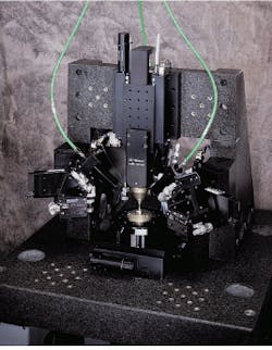
Working with submicron-precision motion control provides many challenges to system designers and manufacturers (see Fig. 2). There are several significant changes taking place for the manufacturers of motion-control equipment used by semiconductor-equipment manufacturers. Industry standards have embraced the 300-mm-diameter wafer and are moving to implement its fabrication techniques. This wafer is almost 50% bigger than current 200-mm wafers; fabrication requires motion-control systems to move over larger areas.In the other direction, standards and technologies are moving toward smaller and smaller feature sizes so that more information can be contained on a wafer or chip. One-half-micron feature sizes are common in manufacturing, with 0.35- and 0.25-µm characteristics in development and smaller linewidths in the research stage. These changes are impacting motion-control systems that are now required to resolve to such smaller features.
The third factor of concern to manufacturers is the constant pressure to improve yields and production rates. Speed, accuracy, and repeatability are all elements that are impacted by these demands. Finally, uptime or MTBF, as well as mean time to repair, are production concerns that are being addressed on the subsystem level. These issues require not only reliability at the component level but also at the system level. More testing is needed along with, perhaps, a systemic approach to integrating components into a system.
Motion-control systems have been incorporated into all aspects of semiconductor and electronics manufacturing--from the front end, where various lithography techniques are performed, including scribing and exposing of the photo resist, to the back end, especially in-process testing, where gantry-style motion places parts in predetermined locations. A similar style of motion is also used for automated dispensing of glues.
Cleanroom compatibility
The semiconductor-manufacturing industry also has driven another set of requirements for cleanroom compatibility, which have spilled over into other applications. These requirements not only impact the way that the components are assembled but also the design of the system. Material selection is important for thermal stability, stiffness, and resistance to change over time (including corrosion and wear), but also for outgassing properties that may contaminate a cleanroom or vacuum environment. Other industries, such as the biomedical industry, have begun to specify cleanroom compatibility, so that outgassing and other potential contaminants, such as certain lubricants, do not endanger biomedical processes.
Motion-control equipment is being interfaced with other subsystems in complex arrangements. Vision systems both control and provide feedback to the motion system, directing it to position a component and then recording an image once it is properly positioned (see Laser Focus World, April 1996, p. 127). Complex systems require facile working relationships between the various design teams, both in the product-design phase and once systems are installed. Manufacturers are improving application-engineering support with people and services to meet these needs.
ACKNOWLEDGMENT
The author wishes to acknowledge the extremely helpful assistance received from Aerotech (Pittsburgh, PA) and Newport (Irvine, CA) in the preparation of this article.

