How the proper positioner keeps fiber aligned
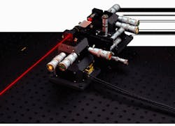
Fiberoptic positioning systems and components are the tools used to align, orient, and make the attachment between a fiber and an optical device such as a diode laser or a waveguide. This equipment can also be used to optimize the performance of an optical device, improving coupling efficiencies and minimizing losses (see Fig. 1).
Positioning equipment can be either manual or automatic and can be designed for either single-mode or multimode fibers. Common positioner tasks include pigtailing diode lasers to couple the light from a diode into a fiber and installing attenuating or polarizing optics in a fiberoptic layout. Such tasks are similar in both research and industrial environments but are different in the degree of automation and the robustness of the equipment.
The factors influencing the decision to select a particular type of fiberoptic positioning equipment include metrology issues, ease of use, durability, and automation required. Of course, cost considerations influence the final decision, although for industrial applications, cost appears to be a less important factor.
This Product Focus briefly describes the components found in typical fiberoptic positioning systems and several methods of system integration. It also reviews aspects of automation used in industrial positioning applications. The table of manufacturers and suppliers that follows on p. 142 is not meant to be a comprehensive listing of all vendors. For a more complete listing, see the list that begins on p. 358 in the 1996 Laser Focus World Buyers Guide.
This is a dynamic market—prospective purchasers should contact the manufacturers for further information about the latest available products. Many vendors provide detailed
discussions on the theory, implementation, components, and systems in their catalogs.
The best way to understand the problem of fiberoptic alignment is to visualize the nature and scale of motion that must be undertaken to connect two small elements properly. Motion can be required in any of six degrees of freedom—in the x, y, or z axes and also in Qx (roll), Qy (pitch), or Qz (yaw), with x as the optical axis. The scale of any adjustment is also important. A single-mode fiber has demanding alignment conditions because its core diameter is only between 2 and 10 µm. To align it with another fiber or an optical system and maintain good power transfer, an alignment tolerance of <0.1 µm (100 nm) is usually required.
To understand the differences between products, you must know the terminology. For example, the term resolution—the smallest increment of motion that the system can discriminate—can refer to the display resolution, what the readout shows, or the position resolution, which may not even be of the same order of magnitude. Repeatability, sometimes called precision, measures the error range observed as a given position is attempted many times. Bidirectional repeatability, the specification for the error range covered by travel in two directions, is a more demanding requirement.
Accuracy—the deviation between the actual component motion and the ideal component motion—is differentiated by some vendors into actual position accuracy and guidance accuracy, the path errors caused by the system itself. Stability, another important criterion, measures how well the system holds position once it is achieved. Stability is a necessary feature because it eliminates the problem of drift during measurement or fiber bonding activities.
System components
Fiberoptic positioning systems are constructed from components; this allows the end user to assemble the system or to purchase an integrated system. The key components include stages, slides, encoders, readouts, and actuators. Many of these components are similar in design to the pieces used in macropositioning systems—the differences being a more limited range of motion and the degree of precision required to achieve the desired position.
Stages. The stage mechanism, which controls motion, strongly influences the capability of the positioning system. Four basic stage designs are available. The simplest, a dovetail slide, consists of two flat surfaces, each shaped like a wedge, that slide against each other. A dovetail slide provides for a long travel distance and can support large loads. However, this design has high friction (which varies with the speed of the stage) and high stiction (breakaway friction). Both factors limit positional resolution. In a system that requires submicron levels of precision, these factors can limit successful operation.
Ball-bearing slides, in which sliding motion is replaced by a rolling motion, have a shorter range of motion but much lower friction and stiction. Their positioning capabilities are much finer than those of dovetail slides, and they are capable of achieving sufficient accuracy for fiber work. They are, however, limited in load-bearing capacity. Crossed roller bearings, in which the ball bearings are replaced with rollers, perform similarly to ball bearings but have higher load capacity and stiffness. These features impart additional stability and robustness to the system, which is very important in operations such as optical-fiber coupling.
The fourth stage type, a flexure stage, has neither rolling nor sliding for motion, but depends upon the elastic deformation of solid parts. The resulting range of motion is very small (less than a few millimeters), but there is neither friction nor stiction because there is no contact between the moving parts. There is a high degree of stiffness and a high load capacity. Besides the short range of motion, another disadvantage is that most flexure systems approximate a straight-line movement with a circular path. That is, there is an arcuate, or arc-like, displacement as the system is moved in translation.
Actuators. Choice of drive mechanism or actuator depends upon some of the same concerns as for stages—repeatability, resolution, range of travel, loading, manual or motorized operation, speed, remote control, and position verification or readout. Manual operation can be controlled by screws, micrometers, or differential micrometers. A screw drive is perhaps the lowest-cost motion method. Resolution is determined by the thread pitch (the number of threads per inch). Precision is governed by the quality of the screw (no burrs or rough spots) and a ball-shaped tip to minimize slippage. Micrometers provide the user with a readout, based on a measurable correlation between a complete turn and the distance moved. Differential micrometers provide both a readout and a resolution in the submicron range achieved by using the difference between two screws for very fine motion control.
Motorized actuators come in three generic versions for fiberoptic positioning: piezoelectric, dc motor, and stepper motor. With a piezoelectric motor, a voltage is applied to a crystalline material (frequently lead zirconate titanate or PZT), and the crystalline material expands proportionally. Response times are very short, and positional resolution is limited only by the noise of the power supply. Total linear-displacement range is small, and earlier designs displayed either hysteresis or nonlinear expansion effects. Newer designs require less voltage and with an active positive feedback control can obtain a positional resolution of a few nanometers.
DC motors are available in either brush or brushless models and are best used where high speeds and smooth operation are required. Positional accuracy is improved with encoders and tachometers. These motors are typically confined to uses in automated systems, where they are used in conjunction with glass-scale encoders, more rigid than metal, for highest accuracy.
Stepper motors drive a screw to create either linear or rotary motion. Using a technique called microstepping, it is possible to create up to 100,000 steps per revolution of the motor. Linking this motor to a fine-thread lead screw or gearbox provides the high resolution and good repeatability for fine positioning of optical fiber.
System selection and automation
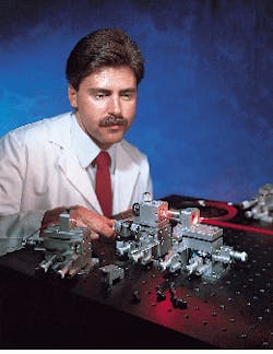
Ultimately, the choice of fiberoptic positioning components depends upon the intended use of the system. In a laboratory environment, where a researcher might be characterizing materials used in a waveguide device, a system with manual alignment and positioning requirements might be sufficient (see Fig. 2). If the same technology were placed in a manufacturing and production environment where the fiberoptic positioning system is used for production test, measurement, and inspection, then a more highly automated system with motorized and computer controls would be appropriate.As the need for high-precision fiberoptic positioning equipment develops in production environments, there is an increasing demand for automation to optimize and secure the fiber alignment with a device. Just as there are feedback loops within the positioning system to minimize positional error, so there are system feedback loops to insure maximized power into a fiber or to optimize output-beam location. Automated positioning systems in manufacturing environments facilitate repetitive tasks.
According to Bernie Walik, vice president of manufacturing at OptoPower (City of Industry, CA), his company's fiberoptic positioning equipment undergoes heavy use in a two-or-three-shift manufacturing environment. He is most concerned with durability and reliability of the systems and also with ease of use by the technicians on the floor. Andrey Okishev, a scientist at the University of Rochester's Laboratory for Laser Energetics (Rochester, NY), uses single-mode polarization-preserving fibers to connect lasers and regenerative amplifiers in a pulse-shaping system for the Omega inertial-confinement-fusion laser. He is most concerned with accuracy, coupling efficiency, and stability. Both users recommend discussing in detail with any potential vendors not only the intended application but likely future uses.

