Multi-axis scanning pushes next-generation steering performance
Tracing back to the Byzantine times, gimbal systems have been a mainstay in pointing applications. Pointing of optical systems can be implemented by mounting their entirety on a moving platform or using a moving mirror as the last optical element. The latter often offers speed and other performance advantages.
Currently, there are three types of devices on the market that use a moving mirror for optical system pointing: gimbal-mounted mirrors, flexure-based fast-steering mirrors (FSMs), and galvanometers. Galvanometers mount a mirror on a rotating axis to perform scanning in a single plane; two-dimensional scanning is done using two galvanometers positioned orthogonally, commonly known as a galvanometer pair or galvo scan head.
Each of these solutions have performance limitations. Gimbal-mounted mirrors that offer the largest range of apertures and scanning field sizes are the slowest due to the larger moving mass compared to galvo scan heads and FSMs. Large moving mass of the gimbal solutions is undesirable in high-speed applications in space environments due to induced disturbance torque on the spacecraft that need to be compensated.
FSMs offer the fastest speed, highest bandwidth, and high angular resolution and accuracy. However, these performance advantages come with a very small scanning field—typically less than ±1° as a result of the limitations of mirror mounting using mechanical flexures and actuator types commonly utilized in these systems.
Galvanometer pairs excel at small apertures and typical scanning fields of ±25°. Galvo pair speed, size, and weight degrade with the increase in system aperture, and are rarely used with apertures greater than 50 mm. Some alignment errors, such as rotational axis orthogonality, are difficult to compensate in galvo scan heads and their pointing drifts with temperature, making their use problematic in defense applications.
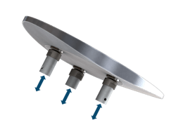
Light Steering Technologies (Manchester, NH) has patented, developed, and demonstrated a 3-axis scanning solution called the Multi-Axis Scanner that offers considerable advantages for large apertures. It uses laterally unconstrained magnetic joints to attach a payload, most commonly a flat mirror, to three linear actuators (see Fig. 1).
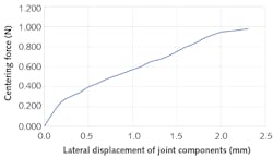
Laterally unconstrained magnetic joints consist of a permanent magnet with a bearing element that has an interface surface as well as a ferromagnetic steel alloy tip with a spherical interface surface, resulting in a point contact between the two articulating joint components (see Fig. 2). The bearing element of the permanent magnet can be a polished nickel plating, bonded sapphire disk, or any other method of improving flatness and durability of the flat interface surface of the magnetic joint.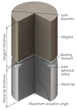
The permanent magnets of each joint are attached to the flat mirror so that the interface surfaces of their bearing elements are co-planar and parallel to the front mirror surface. This enables definition of the mirror orientation using three points of contact between the articulating magnetic joint components; it also allows lateral translation of the mirror without affecting its pointing.
Laterally unconstrained magnetic joints
Components of the magnetic joint are sized based on the weight of the mirror and application requirements such as actuation speed and scanning field size. Typical design would have the axial attraction force capable of withstanding several times the expected environmental and actuation accelerations.
Materials for the magnetic joint components are selected based on the environmental and performance considerations. The strongest commonly available grade of neodymium iron boron (NdFeB) magnets is N52 and would be used in most joint implementations—those requiring storage or operating temperature above 65°C are the exception. For high-temperature environments, an appropriate grade is selected, trading off the axial attraction force within the joint. Figure 3 shows a typical dependence of the axial attraction force on the magnet thickness for two NdFeB grades.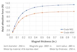
The bearing element material would depend on the joint application. Basic implementation would have a polished nickel coating of the magnet. When a higher precision or joint durability are required, a 50-to 250-μm-thick sapphire disk may be bonded to the magnet.
In most expected environments for a 3-axis scanning solution, ferromagnetic stainless steel would be the preferred material for the joint’s metal tip. Different ferromagnetic stainless steel alloys (those in 400 series) display no appreciable difference in the axial attraction force to the permanent magnet of the joint. Typical magnetic joint tips are made from hardened 430C stainless steel alloy with an optical quality diamond-turned finish of the joint interface surface (see Fig. 4). This level of surface precision minimizes the tolerancing error when translating positions of three actuators into the mirror deflection.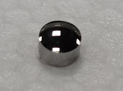
The spherical radius of the metal tip is selected based on the maximum mechanical mirror actuation range, which is calculated from the scanning field size and has no minimal angle-of-incidence requirements of the scanner. In most applications, it would be optimized to minimize the air gap between the joint components and therefore maximize the axial attraction force.
A lubricant is added to the joint, as an application environment allows, to reduce friction and wear within the joint. Additional performance enhancement can be achieved by using a ferromagnetic fluid within the joint air gap for both lubrication and axial attraction force increase.
The laterally unconstrained magnetic joint that lacks rigid mechanical constraint in all but axial directions is a major advantage for athermalization as well as mechanical dynamic response, such as that in a 3-axis scanning solution design. Rapid mirror replacement is an additional advantage for high-power laser application.
3-axis scanning solution design considerations
Typical design configuration of the 3-axis scanning solution based on the laterally unconstrained magnetic joint would have actuators equally spaced on an actuation diameter. And the mirror would be nominally positioned relative to the incident beam so that the angle of incidence is greater than half of the maximum deflection angle and the incident and reflected beams are separated over a full range of deflection angles. Nominal angle of incidence of 45°, resulting in 90° nominal reflection, is expected to be a common configuration for providing the convenience of orthogonal system layout while giving up some performance due to increased mirror size.
This typical configuration would have a nominal plane of incidence; therefore, mirror motion (and resulting light deflection) can be orthogonally decomposed into components parallel and perpendicular to the nominal plane of incidence. The mathematical engine incorporated into the 3-axis scanning solution controller receives the deflection angles from the host system and translates them into the linear positions of each actuator.
The mirror-mounting principle using three laterally unconstrained magnetic joints can be used with a variety of linear actuation technologies and mirror materials. This opens a wide performance trade space when adapting 3-axis scanning solutions to a particular application.
Direct-drive linear motors, such as a voice coil or multiphase synchronous linear motor, offer the best dynamic performance. Ball-screw or lead-screw-driven actuators can be used when the scanner needs to perform in environments that experience high shock or vibration, trading scanning speed for an increase in the system robustness. Piezo actuators can be used in applications with a very limited scanning field.
A typical 3-axis scanning solution actuator design uses linear cross-roller bearings to mount actuators due to their stiffness, low friction, and high precision of motion. Air bearing can also be used for the most demanding applications—particularly in factory environments, where access to compressed air is common.
A 3-axis scanning solution can be used with any linear position encoder technology applicable to the scanner’s operating environment. Optical encoders offer the best performance and can be easily incorporated into 3-axis scanning solution designs for apertures of 75 mm and above. The measurement of actuator position provides a reliable method for determining the pointing of the mirror since there are very few tolerances and other factors contributing to static and dynamic errors. The accuracy of the magnetic joint interface surfaces is achieved at sub-micron level and the tolerance of actuator placement in the assembly can be calibrated out of the overall pointing error. Dynamically, there are no twisting forces within an actuator body, such as those found in a typical galvanometer between the mirror and position detector. This makes it easier to provide a robust structure between the metal tip of the magnetic joint and the linear encoder readout location.
Either absolute or incremental encoders can be used depending on application demands. When incremental encoders are chosen, travel limit sensors are added to the design to provide an absolute reference for actuator homing routine.
With 3-axis scanning solution technology, having the body behind the mirror at the nominal pointing, it’s feasible to implement additional reference sensors that further improve overall system accuracy. One example is a zero-deflection sensor that provides absolute mirror position reference at the nominal or zero pointing. Common sensor implementation consists of a quad cell, laser diode, and a zero-deflection algorithm (implemented on the digital controller). Laser energy is reflected off the flat and added to the back surface of the mirror, the energy will be equally distributed over the quad cell when the mirror is at nominal deflection. Based on the total energy measured in each quadrant, the 3-axis scanning solution can provide closed-loop pointing correction as well as absolute positions relative to the mirror surface at or near the home position. System accuracy may be improved with each home transition where the zero-deflection sensor actively calibrates home from the mirror surface.
Three equally spaced actuators of a 3-axis scanning solution with the same travel range offer an elliptical scanning field, the aspect ratio of which depends on the nominal angle of incidence. In many applications, a 3-axis scanning solution system layout in which the input to the scanner and the nominal output from the scanner are orthogonal is preferable. Such a scanner configuration would have a nominal angle of incidence of 45° and the scanning field aspect ratio of 1:0.7.
Key performance trades scanning systems
Figure 6 outlines the trades from the basic gimbal, gimbal scan mirror, galvo pairs, and fast steering mirror, as well as Light Steering Technologies’ Multi-Axis Scanner specifically. When the application scanning field size does not exceed ~±45° × ~±35°, the 3-axis scanning solution offers size, weight, and power advantages over a similarly performing gimbal-mounted mirror. It can also be optimized for other performance parameters, such as speed or accuracy, to exceed the capability of the state-of-the-art gimbal systems. The advantage of a larger aperture in space applications is having the mass of moving components an order of magnitude less than the comparable gimbal-mounted mirror, resulting in significant reduction of the scanner’s inertial impact on the host spacecraft.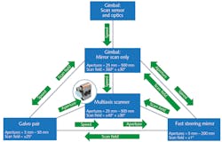
When compared to a galvanometer pair, the 3-axis scanning solution can support applications with apertures greater than 50 mm where galvanometer pair performance experiences exhibit a sharp drop off due to the increasing size and weight of the second mirror. The 3-axis scanning solution also addresses applications in which having single scan point is critical.
The mirror mounting methodology using a laterally unconstrained magnetic joint can overcome the limitation of mechanical flexure commonly found in fast-steering mirror designs and extend the scanning range of such systems while utilizing the same actuator component to maintain other performance parameters.
Another feature of the 3-axis scanning solution is the ability of fast-field replacement of the mirror, which can be useful in high-power laser processing applications where risk of mirror damage is high.
ACKNOWLEDGMENT
Multi-Axis Scanner is a trademark of Light Steering Technologies, Inc.
About the Author
Aaron Castillo
Senior VP of Business Development & Program Management, Light Steering Technologies
Aaron Castillo is Senior VP of Business Development & Program Management at Light Steering Technologies (Manchester, NH).
Vlad Krylov
President & CTO, Light Steering Technologies
Vlad Krylov is President & CTO at Light Steering Technologies (Manchester, NH).