What laser optics designers need to know about high-LIDT optics fabrication
The demand for optical components capable of handling high-power laser beams has grown by double digits in recent years. This growth has been largely a response to the steadily increasing power from both continuous-wave (CW) and pulsed solid-state fiber lasers and disk lasers.
The increasing power of CW and pulsed lasers with millisecond to nanosecond pulse widths has helped drive the growth of laser cutting, drilling, welding, marking, and 3D-printing applications. At the same time, higher-power ultrafast lasers have moved quickly from the laboratory into production. These laser sources with picosecond and femtosecond pulse widths are the basis for new laser-processing applications in semiconductor, electronics, and medical-device production. High-power fiber lasers have also enabled new military applications.
Another important trend is the expanding range of wavelengths, particularly those in the deep UV and visible (for example, blue and green) portions of the electromagnetic spectrum, for which high-power lasers are now available. These are also enabling new applications for materials processing.
Demanding high quality for every component
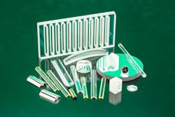
Users of laser optics are demanding ever-higher levels of quality for all applications (see Fig. 1). Variations between components and production batches that lead to unplanned degradation or failure of the laser equipment or the laser process is unacceptable for industrial users and suppliers.
The common approach to specifying quality of high-power laser optics is to define a laser-induced damage threshold (LIDT). LIDT is the maximum value of laser radiation that an optical component will handle with a zero probability of damage. The reader can refer to ISO 21254-1:2011 for information on LIDT testing.
Specifying and testing high-damage-threshold laser (HDTL) optics can be challenging. Many variables affect the damage threshold. Failure is statistical, depending on laser, environmental, and other variables unrelated to the optical component. Furthermore, a component’s perceived reliability can depend on how test data is interpreted.
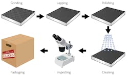
For this reason, it is critical to define the optical component’s requirements up front, as well as a plan for consistently achieving these (see Fig. 2). With clear requirements in hand, the manufacturing team can move forward with confidence to develop a production process that addresses the quality, performance, and cost demands of high-LIDT optics.What fabricators must control for HDTL optics
No matter what laser type or application, the optics fabricator must control defects and other characteristics of the optic to ensure its reliability.
Glass composition and homogeneity. Achieving a consistently high damage threshold begins with selecting the substrate material. Optical properties critical to damage threshold, namely absorption and scattering, vary with composition and details of the glass manufacturing process. For example, low absorption of fused silica correlates to a low -OH content. Striae (local variations in the index of refraction), impurities, and inclusions introduced in glass processing affect the damage threshold through optical interference and absorption effects.
Surface finish. Surface defects, such as cracks, scratches, digs, and voids, reduce the threshold for laser damage. Lower threshold results from localized laser interference, heating, and reduced mechanical strength of the glass.
Subsurface damage. Cracks beneath the surface produced in machining brittle materials, such as glasses and ceramics, reduce the damage threshold as they propagate from thermal stresses generated by laser irradiation.
Residual stress. Stresses locked into the surface and subsurface regions during fabrication can contribute to premature failure of the optic surface through fatigue or aging.
Contamination by residual grinding and polishing compounds. Grinding and polishing compounds from optical fabrication processes may become trapped within small cracks or pits. These can reduce the damage threshold of polished surfaces by reacting with the glass and locally changing its mechanical properties. Residues may also react with the energy source (electron beam or ion beam) during coating of optical surfaces. The reaction products may change the composition of the surface or redeposit onto the optical surface as debris that affects coating adhesion.
Dust, dirt, and other unwanted material. Impurities on the surface may preferentially absorb the laser beam, resulting in heating of the surface.
Coatings. Many laser optics include complex metal or dielectric coatings comprising tens of layers for enhanced reflection (mirror) or transmission (window). Coatings are often designed to reflect or transmit multiple wavelengths—the laser wavelength and others used with cameras and process sensors.
Damage thresholds depend on the materials of both the substrate and coatings and the optical fabrication processes. Coatings may amplify defects in the substrate, so the damage threshold of a coated optic is significantly less than that of the uncoated optic.
How fabricators ensure consistent quality of high-LIDT optics
As noted above, the foundation of reliable HDTL optics is a clear understanding of the application and relationships between the many quality and process parameters. The optics fabricator can be confident in proceeding once they know the requirements (see Fig. 3).Substrate material selection. As noted earlier, the substrate material is key to damage threshold. Material also affects component cost. Glasses differ in machining and polishing rates and, therefore, processing times through their mechanical properties and chemical compositions. Higher purity glasses are usually more expensive.
While fabricating millions of optical components from many materials, an experienced optics fabricator will have learned a lot about the products from major suppliers of optical materials, including the strengths and limitations of the suppliers’ manufacturing processes.
The optics fabricator also brings to a manufacturing partnership expertise to advise the customer’s optical design team on the type and manufacturer of glass that will yield the most consistent performance and an optimum tradeoff between cost and quality. For example, even though published specifications are similar, there can be subtle but significant differences in homogeneity of the material and its properties. Some differences are not even detectable using classical inspection methods. However, they can affect processing behavior and laser-induced damage threshold.
Optical surface fabrication. Preparing the optical surfaces is the most critical step in fabricating HDTL optics. Fabricating precision optics involves complex processes requiring control of mechanical and hydrodynamic forces, chemical reactions, and structural effects on glass surfaces and subsurfaces. Defects (scratches, digs, voids, cracks, and sleeks) and residual stresses on the optical surfaces will affect the finished component’s robustness. These defects will also affect any coatings applied to the surfaces.
The following sections provide a glimpse at how a precision optics fabricator approaches the production of high-damage-threshold optics, considering their cost and quality goals.
Grinding and lapping. Fabrication of laser optics begins with multiple steps of each of two processes: 1) fixed abrasive grinding, and 2) loose abrasive grinding, also known as lapping. Each step gets the optic closer to its finished shape and size.
In addition, each of the steps in grinding and lapping removes open and closed subsurface microcracks, referred to as subsurface damage (SSD), produced in the previous step. A “rule of thumb” in optical fabrication is that the SSD is approximately 0.3X the mean diameter of the abrasive grit or particle. Therefore, each successive step in grinding and lapping uses a smaller grit size to reduce the SSD.
The fabricator will select process parameters, including pressure, velocity, temperature, and type and size of the abrasive particles for the specific optical material being fabricated. The material-removal rate and roughness produced in grinding and lapping vary with the fracture toughness properties of the glass or ceramic. The reaction of optical materials to water and other chemicals used in grinding and lapping also differs.
Polishing, the next process, is time-consuming and not as cost-effective as grinding. Therefore, another goal of grinding and lapping is to minimize the SSD that must be removed in polishing.
Polishing. Many of the considerations for removing material and controlling surface finish in grinding and lapping also apply to mechanical and chemical polishing processes.
The primary goals of polishing high-LIDT optics are to eliminate subsurface cracks and to produce a surface having a finish better than 10 Å root mean squared (RMS). To accomplish this, IRD (Litchfield, MN) uses results of internal and external research. This research documents the relationships between process parameters used in fabricating high-damage-threshold laser optics and the quality of the polished surfaces.
Cleaning. Cleaning throughout fabrication removes lubricants, wear debris, and abrasive agents from rough and fine grinding, lapping, and polishing. Residual debris can interfere with coatings. It can also react with the glass to create local changes in optical and mechanical properties.
Laser optic fabricators use several cleaning methods during processing. These may include:
- Hand cleaning with isopropyl alcohol
- Removing organic compounds through cascaded baths with multiple detergents
- Rinsing in deionized water
- Oven baking to dry components
- Spin drying
- Washing with proprietary solvents to remove organic and inorganic materials
- Hydrofluoric acid etching for stress relief
The ideal cleaning method depends on the material being fabricated and the component’s finish. Scratches are key to determining the laser damage threshold of an optic. Therefore, it is necessary to protect the optic from being scratched during cleaning. It is also necessary to prevent debris (e.g., fibers from polishing) from being added to the surface during cleaning (see the case study below).
In most cases, high-LIDT optics require a customized cleaning process to achieve the application-specific requirements.
Inspection. Since HDTL optics require exceptional and consistent quality, inspection during process development and for quality assurance in volume production is critical.
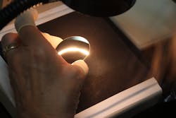
During process R&D, destructive tests are used to document relationships between process parameters and quality metrics. For example, hydrofluoric acid etching is used to determine the depth of SSD in relation to abrasive size and other grinding, lapping, and polishing parameters.Later, in production, optical inspection tools, including those listed below, provide nondestructive evaluation (see Fig. 4):
- Stereo microscope for low- to medium-magnification inspection
- High-intensity lights against a dark background for identifying surface defects
- Interferometer for measuring roughness and for characterizing debris, pits, and scratches
- Interferometer for measuring flatness
- Differential interference contrast microscope for defect analysis
- High-magnification microscope with polarized and unpolarized lighting and stitching capability for large area inspection.
Packaging. Proper packaging preserves the optical surfaces during shipment. In most cases, custom packaging supports the component on its edges or on noncritical surfaces outside the clear aperture. The packaging also prevents the component from shifting during shipment.
Case study: Large-surface-area precision mirror for a high-power laser cutting system
Figure 5 shows a large-area rectangular slotted mirror required by a leading global manufacturer of laser-based machine tools. The customer approached IRD after struggling to find an optic fabricator capable of meeting cost and quality requirements for the mirror.During the design-for-manufacturability review with the customer, the customer agreed to add a bevel to the edges of each slot at the mirror surface. The bevel replaced a sharp edge that would generate fibers on the slot edge during cleaning. Fibers would contribute to coating defects that would, in turn, reduce the damage threshold.
The new design included a 50 µm bevel, the maximum allowable given the required clear aperture.
Even with this small bevel, fabrication required a special cleaning process, one that would avoid creating fibers along the beveled edges of the slots. The small bevel and custom cleaning process have contributed to mirrors that consistently achieve the LIDT specification.
To achieve the cost and volume goals, IRD also invested in process development and in a custom production cell. The cycle time was reduced from more than eight hours per piece initially to less than one hour per piece in volume production through these efforts.
Conclusions
Fabrication of high-LIDT optics requires deep knowledge of material properties and fabrication processes. Through a clear understanding of the application and requirements of the optic, the optics fabricator will create a process that begins with selecting the best material and continues through shipping of the finished component.
About the Author
Todd Anderson
Vice President, Business Development for IRD Glass and IRD Ceramics
Todd Anderson is vice president, business development for IRD Glass and IRD Ceramics (Litchfield, MN).


