Space imager design corrects for Earth’s curvature in the optics

Because the Earth is spherical, imaging large areas of the Earth from spacecraft, or sometimes even high-altitude aircraft, can result in images that are distorted, with a look similar to the barrel distortion produced by some wide-angle lenses. However, just as wide-angle lenses can be designed to correct for barrel distortion as long as the angular field size is not too extreme, spacecraft imaging lenses can be designed to correct for the distortions introduced by the Earth’s curvature. This design process achieves what is called “orthorectification,” or the correction of an image for the object’s topology. (Another complication occurs when images are taken at non-normal incidence to the Earth, introducing tilt, and thus “keystoning.”)
Researchers at Raytheon (El Segundo, CA) and the University of Arizona, College of Optical Sciences (Tucson, AZ) have calculated the amount of correction needed for a space or aircraft camera design to correct for distortion as a function of field of view (FOV) and altitude, and have designed an off-axis, all-reflective f/2.5 optical system with a 2.5 in. focal length and a 70° × 4° FOV, with 13% positive distortion introduced as part of the design to compensate for the Earth’s curvature at an 830 km altitude.1
Doing orthorectification with optics
Although it is quite simple to correct the distortion in an Earth image taken from space by using software to postprocess the image, this approach does not compensate for the fact that, in such a distorted image, the resolution near the edge of the image is actually lower than at the center of the image, due to the fact that the Earth is farther away from the camera in areas near the image edge. In contrast, when orthorectification is done in the optics, the spatial resolution across the image is preserved.
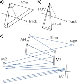
The researchers created their optical design specifically for a satellite taking images in a polar orbit; such satellites typically create images by scanning a 1D array to build a 2D image. This can happen in two ways (see figure): the first, called push-broom, orients the 1D array perpendicular to the satellite’s track, capturing one continuous sweep (requiring no moving parts), while the second, called whisk-broom, orients a smaller 1D array parallel to the track; in this case, the optics repeatedly scan across the track to build a 2D image (requiring a moving scanner). The push-broom approach is mechanically simpler, but needs a larger FOV.
The optical design is a four-mirror off-axis configuration with none of the mirrors obscuring any other and is intended for push-broom operation. In addition, all four mirrors are freeform, allowing aberrations to be corrected to a high degree. The optics, which have a Petzval sum of nearly zero, operate from the visible spectral region to the longwave-infrared (LWIR). It should be noted that the idea of orthorectification in an optical design is not new: one of the researchers previously designed an on-axis f/3.3, 60° FOV mirror system to achieve a similar goal.2 However, the new system is refined and obscuration-free.
The new off-axis design contains a focal-plane array (FPA) 4 × 0.2 in. in size, has a root-mean-squared (RMS) aberration of 0.07 waves averaged over the whole field at a 1 μm wavelength, and has primary and secondary mirror heights of 27 and 13 in., respectively. The researchers designed the freeform configuration using Zernike polynomials up to degree 26. They note that this type of design is especially challenging, as wide-FOV optical designs generally resist being pushed towards positive distortion.
REFERENCES
1. T. P. Johnson, J. Sasian, and L. G. Cook, Appl. Opt. (Jun. 30, 2020); https://doi.org/10.1364/ao.392302.
2. L. Cook, “All reflective wide field of view telescope with beneficial distortion correction,” U.S. Patent 8,023,183 (Sep. 20, 2011).
About the Author
John Wallace
Senior Technical Editor (1998-2022)
John Wallace was with Laser Focus World for nearly 25 years, retiring in late June 2022. He obtained a bachelor's degree in mechanical engineering and physics at Rutgers University and a master's in optical engineering at the University of Rochester. Before becoming an editor, John worked as an engineer at RCA, Exxon, Eastman Kodak, and GCA Corporation.
