Aspheres: Industry 4.0 techniques drive fabrication of prototype off-axis ELT mirrors
“Industry 4.0” is a catchword for wireless and cloud-based manufacturing techniques that are said to be the next wave in modernization of industry. Included in Industry 4.0 are a reliance on the “cloud” for holding and processing data, wireless communications between points and devices in the factory (the Internet of Things), and statistical design and analysis, all of which aid the tight integration of computers and robots into the manufacturing process.
The precision optics industry has already begun using Industry 4.0 techniques, in many cases without using the term. While Industry 4.0 developers might not often be willing to share their hard-won expertise in this area as it applies to commercial optics, discussing a large, one-off optics project can be a different story.
One particularly famous large one-off project of this type is the 39.3-m-diameter European Extremely Large Telescope (E-ELT), scheduled to be completed by 2025 and located in the Chilean Atacama Desert. The visible/near-infrared ELT design comprises 798 hexagonal mirror segments, all of which are off-axis paraboloidal sections about 1.45 m in size with a root-mean-squared (RMS) surface precision of about 10 nm.
Researchers from the System Manufacturing Center at the National Chung-Shan Institute of Science & Technology (Taoyuan City, Taiwan), University College London (London, England), the Laboratory for Ultra Precision Surfaces at the University of Huddersfield (Daresbury, England), and Zeeko (Coalville, England) have completed a contract from the European Southern Observatory (ESO) for which they had to manufacture prototype segments for the ELT, all of which were the most off-axis segments in the telescope from near the edge of the primary.1
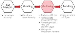
The fabrication was done via computer-numerical-control (CNC) grinding and polishing, the latter of which followed a process called Precessions, developed at Zeeko. As happens sometimes when trying to fabricate large aspherical surfaces, the engineers discovered that mid-spatial frequencies (MSFs) that arose during grinding, in particular in the range of 0.02 to about 1 mm-1, were difficult to remove in polishing. In response, they added an intermediate step between grinding and polishing, called “grolishing,” which in this case was carried out by a hard rotating smoothing tool that preferentially removes the MSF peaks (see figure).
Floating grolishing tool
Rather than using a traditional CNC positioning platform, the engineers decided to use a robot for grolishing due to its much higher speed and lower cost. The lower accuracy of the robot did not matter due to the fact that the 100-mm-diameter grolishing tool was “floating,” held in place by its own weight. Later corrective polishing was done using high-precision CNC.
To increase the accuracy of the computer model, as well as to speed up experimentation, extensive statistical design of the experiment was done and data clouds built for each processing step, with the ultimate objective of having the fabrication equipment choose its parameters without human intervention—in other words, an Industry 4.0 approach.
Five considerations were part of the grolishing statistical model: required volumetric removal rate to finish smoothing in a reasonable time; a resulting surface texture fine enough to pass on to CNC polishing; a smoothing process that does not degrade the overall form produced by CNC grinding; and a grolishing process (tool path, load, etc.) that reduces existing MSFs without introducing new ones.
The experimental runs confirmed that the computer controller for the grolishing process could optimize responses by itself to achieve the specified texture of less than 400 nm, removal rate of greater than 16.3 mm3/min, form and edge RMS of less than 0.3 µm and peak-to-valley (PV) of less than 3 µm, and MSFs of less than 40 nm. In addition, the repeatability of each response was greater than 95%. Zeeko’s Metrology Toolkit software was used to stitch measurements into a topography map for subsequent corrective polishing.
REFERENCE
1. H.-Y. Wu, D. Walker, and G. Yu, Opt. Express (2019); https://doi.org/10.1364/OE.27.021856.
About the Author

John Wallace
Senior Technical Editor (1998-2022)
John Wallace was with Laser Focus World for nearly 25 years, retiring in late June 2022. He obtained a bachelor's degree in mechanical engineering and physics at Rutgers University and a master's in optical engineering at the University of Rochester. Before becoming an editor, John worked as an engineer at RCA, Exxon, Eastman Kodak, and GCA Corporation.