Aspheres: Removing alignment errors from measurements of spherical, aspheric, and freeform optics
Most measurements of optical surfaces include some alignment error, as positioning a part with nanometer-class uncertainty is usually prohibitively expensive. Fortunately, the functional form of translation and rotation errors on a measurement can be calculated, treated as uncertainties, and removed from the measurement. Traditionally, “piston, tilt, and power” are fit, which correspond to the first four Zernike terms (Z0,0; Z1,1; Z1,-1; Z2,0), where Z2,0 is not used for flats.
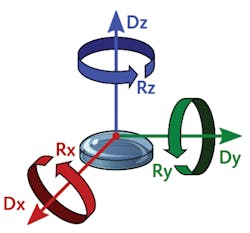
Why does this work? There are just four fitting coefficients, but six rigid motion errors, as shown in Figure 1 (and up to two more when considering interferometer absolute phase uncertainty and radius of curvature error). Here, surface symmetry holds the answer. For a flat surface, Dx, Dy, and Rz have no effect on the measurement, leaving only Rx, Ry, and Dz as fitting terms. For spheres, five of the six motion errors (all but Rz) have an effect, but pairs of them have the same effect on the measurement (see Fig. 2a). For example, Dx and Ry both contribute to the Z1,1 fit term—thus, they cannot be independently solved for. This dependence is also referred to as degeneracy, which will be denoted with curly braces{}—for example, {Dx, Ry}.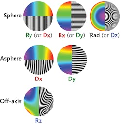
This fitting also requires no assumptions about the part—the surface prescription is not needed to fit the alignment error. This, too, seems counterintuitive—shouldn’t the alignment errors depend on the shape of the part? Actually, they do, but an approximation eliminates the part dependence for low numerical aperture (NA) spheres. The Z2,0 (power) fitting term approximates the actual function (1 – ρ2 NA2)1/2, where NA depends on the prescription.1
Note that a radius of curvature error and longitudinal translation have approximately the same functional form and are thus also degenerate. Distinguishing between these effects is important when radius or power deviation are toleranced separately from surface irregularity. This is allowed by the ISO 10110 drawing standard,2 and is quite common in practice. To separate these errors, the position of the surface at point focus (also referred to as “cat’s eye”) can be measured (as per a traditional interferometric radius measurement).
Alignment errors on aspheres
Fitting alignment error is more complicated on aspheric surfaces. The degeneracies between alignment errors are broken—Ry and Rx still just introduce tilt (Z1,±1), but Dx and Dy introduce higher-order terms (third-order coma Z3,±1 is most common; see Fig. 2b). The rotation and decenter can now be separated in the fit, and the exact proportions between the coma and tilt are not important—or are they?
Consider two 50 mm aperture aspheres with the same best-fit sphere: one with 1 µm of fourth-order departure and the other with 100 µm. What happens if 1 µm of Z3,1 figure error is introduced while fabricating the part? For either asphere, this figure error can be removed by adjusting Dx and Ry. The difference is how much: the 100 µm asphere requires Dx ≈ 0.05 mm, while the 1 µm asphere needs Dx ≈ 5 mm. While the decenter in the measurement is uncertain, it probably isn’t that uncertain. Furthermore, 5 mm is likely to be outside the allowable tolerance for decenter/wedge. This illustrates that degeneracy is a sliding scale—for the 1 µm asphere, {Dx, Ry} and {Dy, Rx} are nearly but not completely degenerate (while they are completely degenerate on a sphere). Thus, it is important to monitor the fit coefficient magnitudes for physically unrealistic values.
Dz and radius of curvature exhibit a similar effect (degenerate on spheres, but not aspheres). For a fourth-order asphere, fitting piston, Dz, and radius of curvature entirely removes three Zernike terms from the measurement (Z0,0, Z2,0, Z4,0); note that unlike spheres, Z4,0 (primary spherical aberration) is removed. The Dz and radius fit values, however, can also be physically unrealistic (1 to 10+ mm). Taking a point focus measurement helps control this uncertainty when included in the fitting analysis, preventing Z4,0 from being inappropriately removed.
Radius fitting on aspheres and freeforms has another subtlety that affects surface irregularity. Consider a parabolic surface shape, which could be represented with a conic equation or as a sphere plus a polynomial. Both representations have a radius term “R” that could be fit (to separate power/radius error from irregularity). For a given measurement (that includes some power deviation), the irregularity will be different after radius fitting, depending on which representation was used—even though the equations represent the exact same shape. For example, if a parabola with both radius and aperture of 100 mm has 1 µm of Z2,0 in the measurement, the different representations result in a 30 nm change in Z4,0 irregularity after radius fitting.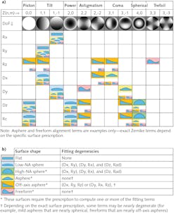
Alignment errors on off-axis aspheres and freeforms
Unlike for rotationally symmetric surfaces, the Rz alignment term now has an impact on freeforms and off-axis aspheres. For example, Rz primarily introduces a particular combination of tilt, astigmatism, and coma (Z1,-1, Z2,-2, Z3,1) on an off-axis parabola (see Fig. 2c). Thus, all the alignment terms affect the measurement, and each looks different, so fitting appears straightforward. When fitting all the terms, however, some result in very large values, suggesting some underlying degeneracy. Yet, no pair of fit terms look alike—so what is going on here? It turns out there is a three-term degeneracy, where Rz is the same as a combination of Dx and Ry, or {Dx, Ry, Rz} for a parabola off-axis in Y (for X, the degeneracy is instead {Dy, Rx, Rz}). These three terms cannot be unambiguously fitted—therefore, one should be dropped.
Freeforms can have even more complicated alignment functions, depending on the surface prescription. Generally, the terms are not degenerate, but if the freeform is very close in shape to an off-axis asphere, it is possible for terms to be nearly degenerate (and cause problems similar to the mild asphere example given earlier). For example, a particular freeform polished and measured at QED had an Rz alignment form that was approximately -Z2,-2 + 0.4 Z3,3 + 0.3 Z1,1 + 0.2 Z3,1 (similar to an off-axis parabola, but also including trefoil).
As a reminder, these Zernike terms are not to be fit individually and removed—rather, the entire function (with a specific proportion of Zernike terms) is removed. Not fitting the proper function causes irregularity to be incorrectly assigned to alignment. In fact, the fitting function need not be represented with Zernike terms at all. For example, the QED.NET Toolkit3 internally represents the fitting functions as height maps and the fit coefficients reported aren’t Zernike terms, but are instead actual surface translations and rotations (in lateral and angular units, respectively).
Conclusions, assumptions, and caveats
While fitting alignment errors on flats and low-NA spheres is simple, more complicated surface geometries introduce additional challenges in the fitting process. Listed below are some key points related to alignment error fitting:
- Not selecting the proper fitting functions causes irregularity to be incorrect. Make sure the proper fitting functions and degrees of freedom are employed to avoid under or overfitting.
- Simply fitting “piston, tilt, and power” is insufficient for any surface more complicated than a low-NA sphere. In general, the fitting functions depend on the surface prescription.
- As surface complexity increases, each fit degree of freedom (DoF) can require multiple Zernike terms to represent the alignment function; Figure 3a summarizes this. Use fitting functions corresponding to each DoF rather than removing Zernike terms.
- The effect of radius fitting depends on the surface representation—the exact same surface shape exhibits different radius fitting behavior, depending on the mathematical equation used to describe it.
- Watch out for nearly degenerate fitting terms (especially on milder aspheres/freeforms): surface irregularity can be erroneously assigned to alignment/radius error and may result in alignment values outside tolerance. Figure 3b summarizes fitting degeneracies by surface type.
- Accurate fitting relies on optical distortion being compensated (or insignificant). For example, uncorrected third-order distortion on a measurement with some tilt will incorrectly add coma (Z3,±1) into the irregularity.
Some metrology systems, such as the Aspheric Stitching Interferometer (ASI), automatically account for most of these points. In other cases, the metrology data should be carefully analyzed to manage alignment fitting issues. This can of course be achieved with custom analysis software. Alternatively, the QED.NET Toolkit includes alignment error fitting functions and a variety of other tools useful for metrology data analysis.
REFERENCES
1. P. de Groot, T. Dresel, and B. Truax, Surf. Topogr. Metrol. Prop., 3, 044004 (2015).
2. Optics and Photonics – Preparation of Drawings for Optical Elements and Systems – Part 5: Surface Form Tolerances (International Organization for Standardization, 2015).
3. “QED.NET,” QED Technologies, https://qedmrf.com.
About the Author
Paul Murphy
Senior Optical Engineer, QED Technologies
Paul Murphy is a senior optical engineer at QED Technologies (Rochester, NY).
Chris Supranowitz
Senior Applications Engineer, QED Technologies
Chris Supranowitz is a senior applications engineer at QED Technologies (Rochester, NY).
Jacob Siegel
Ssenior Software Engineer, QED Technologies
Jacob Siegel is a senior software engineer at QED Technologies (Rochester, NY).