LASER BEAM COMBINING: Coherent-beam coupler self-aligns
David A. B. Miller, of Stanford University’s Ginzton Laboratory (Palo Alto, CA) and a codirector of the Stanford Photonics Research Center, has created what he calls a self-aligning universal beam coupler. The device, which includes photodetectors and electrically controlled phase shifters and variable reflectors, has many guises. All of them combine a number of mutually coherent (but with varying phase shifts and intensities), monochromatic, singlemode-like beams and combine them into one singlemode-like beam using a step-by-step progressive procedure rather than a more conventional global iterative process.
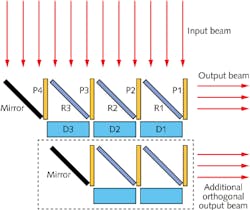
In its most easy-to-grasp configuration, the device can be depicted as an assembly of bulk optics that combines beams varying only in the lateral direction (see figure). Note that although the setup in the figure is dividing a single input beam into fourths and combining them, it could just as easily be combining four beams.
The device contains multiple phase shifters (P1 through P4), variable reflectors (R1 through R3), and detectors (D1 through D3). The P1 phase shifter is optional, used only for phase-shifting the output beam if desired.
The beam-combining procedure is straightforward and is only done once. It goes as follows: 1) Adjust P4 phase to minimize D3 signal; 2) adjust R3 reflectivity to minimize D3 signal; 3) adjust P3 phase to minimize D2 signal; 4) adjust R2 reflectivity to minimize D2 signal; 4) adjust P2 phase to minimize D1 signal; and 6) adjust R1 reflectivity to minimize D1 signal. Low-speed electronics—even simple analog systems—could be used to implement the procedure (which is done as often as necessary to keep the time-varying nature of the four input beams).
When the procedure is completed, the result is always one output beam carrying all the power (minus optics losses) of all the input beams.
Multiple orthogonal beams
In another configuration, the device can serve to separately combine segments of additional parallel beams entering the input apertures, as long as those beams are orthogonal to the first set of input beams.
In this case, “orthogonal” does not mean the beams are spatially perpendicular to each other, nor does it refer to orthogonally polarized beams; the word is instead defined in the way it is used in the world of communications (such as fiber-optics and radar). By this definition, a set of orthogonal beams is one in which each beam is modulated at a different rate so that when any particular
beam reaches its peak intensity, all others are at the trough (zero intensity); this condition can be made to occur for all beams at once.
To achieve this additional operation in the beam-combining device, another layer of components is added to the first, with the caveat that the intermediate array of detectors must be mostly transparent (such detectors exist in the form of silicon defect-enhanced or internal-photoemission detectors).
A property of orthogonal beams is that if one of the beams is coupled by a lossless beam coupler into a single output mode, the other beams must not be coupled into the same output mode. As a result, each orthogonal beam (or set of beams) can be coupled out into a separate singlemode output.
Integrated-optics form
Although depicted as bulk optics, the device would much more easily be created in integrated-optics form as waveguide devices. In this case, Mach-Zehnder interferometers can serve as both the adjustable reflectors and the phase shifters. The many input beams can be coupled into the device via a bulk-optics lenslet array above the integrated-optics chip, and a grating coupler at the end of each input waveguide.
Such a setup is especially easy to create for use with a very large number of input beams in a 2D array, as the lenslets and grating couplers can be readily placed in 2D arrays.
Most losses in an integrated-optical version would result from coupling the beams into the waveguides; some loss will occur due to the fact that each input beam segment will not actually have uniform phase and intensity.
Possible uses for the device include coupling of complex beam modes into singlemode fibers, and coupling a beam into a fiber when the single large input beam (cut into segments by the coupler) undergoes misalignment and/or defocusing; for example, if the source is constantly under motion.
One thing this self-aligning universal beam coupler could use, though, is a compact, easy-to-remember name (the acronym—SAUBC—is not that catchy). Perhaps self-aligning universal coupler-effector (SAUCE)?
REFERENCE
1. D.A.B. Miller, Opt. Exp., 21, 5, 6360 (Mar. 11, 2013).
About the Author
John Wallace
Senior Technical Editor (1998-2022)
John Wallace was with Laser Focus World for nearly 25 years, retiring in late June 2022. He obtained a bachelor's degree in mechanical engineering and physics at Rutgers University and a master's in optical engineering at the University of Rochester. Before becoming an editor, John worked as an engineer at RCA, Exxon, Eastman Kodak, and GCA Corporation.

