Commercial and industrial uses for diode lasers have dramatically increased. Their properties and benefits have encouraged applications in telecommunications, cable-TV transmission, and medicine, as well as continued use in research environments. Output powers have increased significantly, while prices have declined. Diode lasers have unique design constraints. Their optimal operation is sensitive to both operating current levels as well as operational temperatures.
Changes in the current or temperature, either transient or long-term, can significantly impact the lifetime and operating characteristics of a diode laser; both characteristics affect the wavelength and therefore must be adjusted in concert. Thus, it is important to select the appropriate diode-laser controller (or driver), both to ensure accurate and predictable output from the laser and to protect the investment in the device. Controllers can be supplied by the diode-laser maker or by another firm that will furnish them with compatible connectors and features, such as noise protection, for a particular wavelength range.
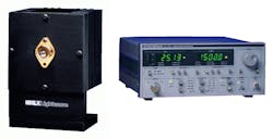
This Product Focus examines the ways that diode lasers can be controlled. The article first looks at current control, both fixed and variable. Temperature, its control and importance to both the performance and life of the diode, is also covered, followed by safety and electrical protection issues. Finally, devices that do both in one package are discussed (see Fig. 1).
A partial listing of manufacturers of diode-laser drivers and sample products follows on p. 138. A more complete listing is available in the 1996 Laser Focus World Buyers Guide, beginning on p. 272.
Current control
A diode-laser driver regulates the current source going into the diode. There are two ways to handle this current. The input current can be constant. As a result, the output power varies, because the diode does not operate at 100% efficiency. A decline in the output power occurs because the heat load created by the diode increases at the diode junction.
Alternatively, the input current can be varied so that the output power of the diode is constant. This method requires the use of a feedback circuit that compensates for the temperature buildup, providing stable optical intensity. Such control techniques provide a starting point in the design of diode-laser driver systems.
Diode drivers should provide an independent current limit. Once this limit is set, it overrides any condition that could cause the output current to exceed the maximum rating for the diode. The current limit is hard-wired into the system, but some computer programs can provide a power limit that has a similar effect. The key to using such software properly is knowing the responsiveness of the photodiode that senses the output power and, thus, setting program limits appropriately.
Very-high-power diode lasers have unique driver requirements (see Fig. 2). These drivers must provide the high current loads required to power these diodes, up to 120 A pulsed or 30 A CW. The drivers contain a pulse generator that can be adjusted for amplitude, width, and pulse-repetition frequency and come with current-limiting controls. At such power levels, the drivers are utilitarian and are designed more for the OEM market.Temperature control
Temperature control is a very important aspect of diode-laser operation; diode-laser lifetimes are inversely proportional to the environmental operating temperatures. Lifetimes improve by an order of magnitude for every 30°C of temperature reduction in the diode-laser case. Thus, there is a powerful incentive to keep the case temperature low. Diode lasers, with up to 30% of their input power converted to light energy, are much more efficient than most other types of lasers. But they still produce a great deal of heat that must be dissipated and removed from a relatively small area. This heat energy generally is removed in two steps--from the diode to the case and then from the case to the atmosphere.
For many low-power CW diode lasers or for pulsed diodes operated at low repetition rates and narrow pulsewidths, passive heat removal is sufficient. An external heat sink is the common form of passive heat removal. The device is typically a sheet of copper or aluminum, which is in thermal contact with the case of the diode. While exotic materials such as diamond can be used, the heat loads usually are low enough to be handled by less expensive metals. The heat is transferred to the plate and then to the atmosphere. The addition of fins on the heat sink can aid in this transfer.
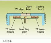
High-power diode lasers, whether pulsed or CW, usually require additional temperature control. Thermoelectric (TE) coolers are the accepted means for removing this heat (see Fig. 3). The principle behind TE coolers, described by Jean Peltier 160 years ago, is that an electrical current, passing through a juncture of dissimilar metals, can either create or absorb heat, based upon the direction of the current flow. With the diode mounted to this type of device, the higher heat levels associated with high-power diodes can be re moved. Excess heat is then moved to an external heat sink, which is cooled by either air or water. Additional cooling can be achieved by the inclusion of additional thermocouples in the TE module.Case temperature can be measured using a variety of sensors including thermistors, integrated circuits, and remote temperature detectors. The thermistor is most common because of its small size and rapid response time. Care should be taken in positioning the sensor to make sure that the temperature is measured appropriately.
The TE cooler is governed by a diode temperature controller that regulates the rate of cooling. As with a diode current driver, the temperature controller could be run by a dc current source, but such a source would not provide sufficient control to optimize the operation of the diode. Temperature controllers also employ feedback loops that maintain the temperature to within several thousandths of a degree and achieve equilibrium very quickly.
Other performance concerns
Electrical noise, especially in the form of current transients, impacts the performance of the diode laser. Noise can distort readings and alter output, as well as damage the diode itself. It is important, therefore, that the diode driver be designed to produce the lowest noise output possible. It is also crucial that the design of the temperature controller take noise into account, because any noise from this controller can couple into the diode driver.
The temperature and current-control system should also be designed for long-term stability. Even though the circuitry is intended to precisely control the diode performance, compensation for long-term drift of the entire system must be planned. The diode driver and the temperature controller can be equipped with GPIB/IEEE-488 or RS-232C ports for computer interfaces. These standard connections facilitate remote data collection and system control, which is especially helpful for establishing automated operations and routines.
Safety and protection
Diode lasers are vulnerable to a variety of transient electrical currents, any of which can either shorten the life of or permanently damage the laser. During powering-up, transients in the initial current surge may reach the output of the laser. Circuit designers generally protect against these surges by use of a slow-start circuit and other protective filters, which serve to reduce or eliminate ac line noise. Shielded transformers also provide further protection.
Noise reduction is sometimes accomplished by means of capacitive filters. These filters pose a risk to the diode if an intermittent or momentary open circuit occurs. An open circuit may be caused when a poorly connected cable is jostled or a solder joint is improperly made. An intermittent open circuit will cause the capacitance initially to charge and then discharge rapidly when the connection is re-established. The result is a potentially damaging large transient. Recent designs in many systems recognize the difference between a high impedance load, which can be accommodated, and an open circuit, which results in the output being turned off immediately.
The diode-laser driver circuit should also be constructed with an output relay that maintains the laser leads at the same potential. The purpose of this relay is to prevent an imbalance while connecting the leads.
One other safety issue must be mentioned, even though it is not affected by the design of the diode driver or the temperature controller. Diode lasers are very sensitive to electrostatic discharge and must be handled appropriately during transport and storage. The work area should be designed with appropriate floor coverings and static protection. Workers and anyone handling the devices should wear grounded wrist straps. All tools that come in contact with the diode laser should also be grounded.
Convenience packaging
In response to general market pressures, several manufacturers have integrated the temperature controller and diode driver in the same package. This common packaging provides convenience for the experimenter or researcher by combining several devices together.
These manufacturers stress the ease of use and flexibility of the controller, especially for performing programmed CW scans. These systems may not be suited to handling very-high-current requirements, but they do provide a tool that frees the general researcher from system design, thus expediting the actual research task.


