Resolving damage ambiguity and laser-induced damage threshold (LIDT) complications
There are many ways in which an optical component can be damaged from laser exposure. While the ISO 21254 specification attempts to define and demystify this damage, the resulting laser-induced damage threshold (LIDT) specification this standard yields is a broad guideline, which may or may not be enough on its own to truly help the user understand an optical component’s real performance.
Because not all optics are manufactured in the same way, and because different industry-specific applications demand components with a diverse number of specifications and unique acceptable quality limits (AQLs), laser-induced damage is a complicated term. For this reason, it is important to communicate your specific application information to your optical component supplier to understand how their LIDT specifications will correlate to your real performance.
ISO 21254-1:2011 and LIDT
The LIDT specification is the energy or power density limit that can be tolerated by an optical surface before it becomes damaged. This specification can be used to compare how well surfaces with characteristically different properties react to laser radiation of a given beam size and fluence. The International Organization for Standardization only defines two types of damage in the ISO 21254-1:2011: surface and bulk damage. They are defined as “any permanent laser-radiation-induced change in the characteristics of the surface [or bulk] of the specimen, which can be observed by an inspection technique and at a sensitivity related to the intended operation of the product concerned.” Without knowing the “intended operation of the product” and then adjusting the “inspection technique and sensitivity” to match the requirement, the LIDT measurement itself might miss important but subtle effects, or it might be overly stringent and drive up costs unnecessarily. The uncertainty in the LIDT specification can, however, be reduced to some degree.
One such unknown requirement to determine LIDT is often the beam size, which can vary from a few microns to nearly a meter, depending on the application. LIDT is generally limited by defects within or on the surface of an optic and has an intrinsically large amount of variability due to its probabilistic determination. In addition, the numbers, locations, and nature of defects will vary from part to part or from run to run in a production process. As such, there is no guarantee that an optical component exposed to a beam with the same size and the same energy or power as the test beam will not acquire damage.
Using the current LIDT specification to advantage
Given an appropriate damage model and a testing environment similar to the actual use environment, an LIDT specification may be used to estimate the LIDT of a different system. If a specified LIDT was measured using a wavelength, pulse duration, or diameter different from that of the intended real application, the LIDT must be re-evaluated for the real application specifications for it to be accurate.
While there are helpful correlations available for approximately scaling LIDT values to a different beam diameter (d), wavelength (λ), or pulse duration (τ), correlations such as the equation below begin to deviate from accuracy quickly as properties deviate from those of the test conditions.
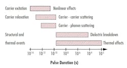
As such, there are very tight restrictions on how much each of these values can deviate from the test values for this approximation to be accurate. In general, LIDT should not be scaled using a wavelength that is ±5% of the test wavelength, a pulse duration that differs from the test pulse duration by a factor of three, or a beam diameter that differs from the test beam diameter by a factor of two. These limits are rough guidelines to ensure that a scaled LIDT is still accurate. Changing any of these three factors will not only affect the likelihood of damage occurring, but can also change the mechanism (see Fig. 1).
Exceptions to these rules do exist. For example, an LIDT specified at a wavelength of 1030 nm may be scaled accurately for use at a nearby wavelength such as 1060 nm because we can assume that the material response changes slowly with wavelength. This assumption does not always hold, however. For example, laser energy near 1550 or 940 nm can be strongly absorbed by water molecules within the material or coating, leading to significantly reduced LIDT. Ultraviolet wavelengths are another such case in which LIDT does not scale gracefully with wavelength.
Damage types
Laser-induced damage, as defined in the ISO 21254-1:2011 specification, only equates to a loss in performance in a customer’s application when that customer actually dictates how the inspection is to be performed and to what level of quality a component must be specified. This is why customer-supplier communication is crucial to obtaining components that perform as expected. Understanding what types of damage will actually impact performance in an optical system, in addition to the damage mechanisms, will allow customers to communicate their application-specific specification requirements effectively. Customers will, in turn, save money by not over-paying for over-specified components.
Nonpropagating defects. These are one type of optical defect usually found during LIDT testing that do not grow or worsen over time. These defects are typically caused by submicroscopic inclusions of an absorbing material such as silicon monoxide (SiO) within a bulk volume of silicon dioxide (SiO2), much smaller than the smallest dig in the scratch-dig specification. These tiny defects (or surface contaminations) become ejected and vaporized by the laser, scalding the surface and changing the color in a characteristic ring pattern. Such a defect on the surface of an optic can produce what is known as a plasma scald, which becomes visible under a differential interference contrast (DIC) microscope. While nonpropagating defects are considered damage, defects such as the plasma scald do not necessarily correspond to a reduction in component performance (see Fig. 2).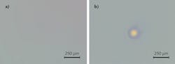
While this type of defect may or may not be visible to the eye and does not reduce the performance of the component, it is still technically considered a type of damage, according to the ISO specification, unless the inspection is adjusted to exclude them.
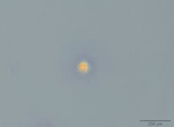
Propagating defects. Depending on the manufacturing process, propagating defects are typically on an optical surface, but are also occasionally present within the bulk glass material as well. These defects are typically the result of leftover platinum particles from the glass manufacturing process. When struck with high fluence, the material surrounding the defect becomes superheated and is ejected from the surface of the optic. As the material cools, it falls back down onto the optic surface, depositing on the surface in an unintended location and creating new potential damage sites (see Fig. 3).
In addition, it is common for undetectably small damage effects to grow, very slowly, into larger problems over thousands or even millions of subsequent shots. This slow growth process is sometimes referred to as damage incubation. The number of shots over which an optic is to be tested is another variable that can have a great influence over the cost/performance ratio of a component. The generality behind the LIDT specification may at first seem like a benefit to the specification, being that it can be attributed to any number of optical surfaces. Consider, however, that there are infinitely many ways in which to cause and detect laser-induced damage and, if the test environment is not as close to the environment of intended use as possible, the LIDT values measured may be irrelevant, making it difficult for manufacturers to create a standard stock product with a one-size-describes-all LIDT value.
Application-specific safety and quality
A safety factor, which is intended for the LIDT to be multiplied by, is a factor that has been empirically determined and is used to select a laser optic more conservatively. Specifying an LIDT higher than that of the energy density of the laser used in an application is one way that laser system designers ensure a lower chance of damaging an optic in the face of all this uncertainty. This helps to keep operation within a regime far from where probable damage may start to occur, but increases the cost of the optics beyond what may be truly required.
What is most important for the end user to address is the limit of quality that is acceptable for the intended application; this is commonly called the acceptable quality limit (AQL). For example, laser optics intended for satellite laser communication that, once put into space, will not be able to be serviced, require some of the highest-quality optical components, with extremely high AQLs on the specifications provided.
What this means is that LIDT testing, which is commonly carried out by striking perhaps 100 sites on an optical surface with tens or hundreds of shots each, might need to be conducted by testing thousands of sites with millions of laser shots. This also inevitably means significantly higher testing costs and component prices. This method of testing can capture subtle failure modes and time effects in the LIDT specification by taking into account defects that are only sparsely distributed over the sample, or defects that develop slowly or do not immediately affect performance. However, for applications in which the optic can easily be replaced if such an unlikely event should occur, the added costs of rigorous testing may not be worthwhile.
For this reason, it is highly recommended that customers and end users maintain positive vendor-customer relationships and that customers communicate with their optical suppliers. An LIDT specification cannot be comprehensive when the requirements of the end customers are variable—it is imperative for customers to discuss their application-specific requirements, such as inspection method, AQL, and lifetime, with their vendor. Until a comprehensive damage specification is created to describe the surface of an optical component, the best way to ensure that a component will perform as expected is to communicate the component needs to those that manufacture and test the components in the first place.
About the Author
Nathan Carlie
R&D Manager, Edmund Optics
Nathan Carlie is R&D manager at Edmund Optics (Barrington, NJ).
Kyle Firestone
Technical Marketing Engineer, Edmund Optics
Kyle Firestone is technical marketing engineer at Edmund Optics (Barrington, NJ).