Test equipment designed specifically for verifying the performance of fiberoptic components has been used in laboratory environments, and many specialized tools have been developed for field-testing system installations (see Laser Focus World, Aug. 1996, p. 125). Manufacturers also have to meet testing requirements at the component level and have modified equipment designed for other applications to adapt it for testing fiberoptic components. As demand for these components has increased, manufacturers have begun to move toward increased automation in factory environments. This is now becoming true in the manufacture of wavelength-division multiplexing (WDM) and dense-WDM components, an application for WDM technology that is just beginning to be commercialized.
As telecommunication traffic increases—fed by rapid growth in use of phones, faxes, home offices, computer networks, and the Internet and the World Wide Web—fiber capacity will have to keep pace. Wavelength-division multiplexing is a promising solution for increasing capacity on long-distance telecommunication links. A WDM system can be compared to a highway transportation system that has multiple lanes for traffic—it provides multiple wavelengths to carry optical signals simultaneously through a fiber.
This Product Focus briefly describes some of the testing equipment used by manufacturers of WDM devices. Because these devices are wavelength-dependent, complete testing of them requires multiple-wavelength sources and detectors, and these are reviewed. Some of the key testing parameters and concerns are covered as well as some of the issues that engineers setting up a testing facility must address. Turnkey systems are also discussed. The market for WDM test equipment is developing rapidly, and there is not yet a standard technical solution for testing. Prospective purchasers should contact device manufacturers for further information about their latest products and their development efforts. A more complete listing is available in the 1997 Laser Focus World Buyers Guide beginning on p. 417.
It is helpful to review some of the components used in a dense-WDM system. The specifications and capabilities of these devices dictate some unique and demanding test requirements. Also, some of the system components that require testing must also be used in the design of the test equipment. In this article, the acronym WDM is used to describe multiplexing components as well as the systems that incorporate these devices.
Sources
Most commercial fiberoptic systems that transport data or voice communications use a single laser optical carrier operating at either 1310 nm or 1550 nm. Early uses of WDM were in systems that operated at both of these wavelengths, thus doubling the capacity of the link. Dense-WDM (DWDM) systems, on the other hand, have several laser sources clustered around one of these lines (usually 1550 nm) with frequencies only a few nanometers apart. The frequency band is dictated by the 1540- to 1565-nm bandwidth capability of the erbium-doped fiber amplifiers (EDFAs) increasingly used to boost transmission distance. Currently, commercial systems have two or four channels, but researchers are studying systems with up to 64 channels. Channel spacing gets tighter as the number of channels increases.
The laser source in a WDM system is usually a distributed-feedback laser diode with direct amplitude modulation. The key concerns are that the wavelength of the laser falls in the center of the channel wavelength and that the output wavelength stays there. The first concern is addressed by fine-tuning the system during the production process, the second, by temperature-tuning the laser diode. Laser sources are used in the test equipment as well as in the installed systems, because some of the components must be tested at the operating wavelengths.
When setting up a test station, the engineer has a choice regarding the laser source. It is possible to choose a separate source for each wavelength of interest, in which case, a four-channel component would require four unique sources to test it. The trade-offs between the options include cost, flexibility, speed of testing, and accuracy of the wavelengths of interest. The test station could also be set up with a single source that is temperature tuned across the spectrum of interest. In either case, it is important to determine that the laser sources are generating the desired wavelength(s). It is not sufficient to assume that they will retain their initial setting. An independent calibration source, such as a stabilized HeNe laser, and a system for laser spectral analysis are usually required, as well as test procedures to recalibrate daily.
Amplifiers, multiplexers, and demultiplexers
The EDFA is a key component in fiberoptic systems. It can be used as a booster and preamplifier, providing transmission distances of 300 km or more without repeaters. If used as an in-line amplifier, an EDFA enables dispersion-limited transmission distances of about 80 km, again without repeater stations. The component must also be characterized for differences in gain across its optical spectrum. Differences of only a few decibels across the
6?8-nm bandwidth of interest can critically impact the performance, especially over long distances with many EDFAs cascaded in the transmission line. A measurement of the gain flatness or gain tilt (both terms are used) will allow for compensation either by using gratings in the fiber or by adding a pre-emphasis to the signal before it is introduced into the link.
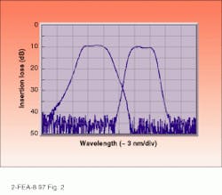
The multiplexer creates the channels in a transmission system, and the demultiplexer separates the various channels at the system's receiving end. Both devices can also be used to separate and route channels at intermediate stages in the fiber circuit, as channels are added or removed. These devices need to be characterized for insertion losses. The losses occur at several points—at the point of coupling to the fiber, in the waveguide itself, at the split, and as a function of its polarization dependency (see figure). To some degree, the system can be adjusted to compensate for these losses.These characterization tests can be used to establish a "go-no-go" point during manufacture, at which a component can be rejected if the losses are too high. The losses must also be tested and characterized as a function of the changes in polarization. As part of measuring loss, the test system looks at power, both at the device level and through the components. A multichannel power meter is the tool frequently incorporated into a test station to support these requirements.
Test systems must also measure crosstalk between the optical channels. Crosstalk is unwanted noise coupled into a channel from adjacent channels; it is undesirable because it adds to the bit error rate of the transmission system.
Many WDM devices are temperature-dependent. The central wavelength will change as the temperature changes. This feature is the means by which the sources are tuned and devices are optimized. An environmental test station with a temperature-control feature can tune and optimize as well as characterize such components.
Automated testing
Factory automation is a goal for of several device manufacturers as DWDM moves out of the laboratory and test facilities into manufacturing for commercial markets. Automation of many of the steps in the manufacturing process, including testing, can improve yields and reduce manufacturing costs. Devices get tested several times: during incoming inspection, packaging, environmental cycling, and quality-assurance sampling. The more that the testing process can be automated, the less probability there is for testing errors and the greater the likelihood that testing costs will be reduced.
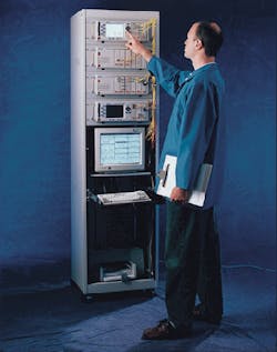
A test station can be a complex device, if it is designed to accomplish all of the testing described in this article (see photo). Test stations are computer-controlled, to allow for semiautomation of the testing process and to record the output, defining each tested component. Software that controls the testing process should be flexible enough to be customized to meet particular manufacturing requirements. The software should have the capability of a hierarchy of controls, limiting programmable access to a select few.
Users should also pay particular attention to the set-up and optimization of the data-management portion of the testing system. Does one computer control more than one test station? Can a centralized data-storage facility be incorporated in the layout, allowing for tracking processes, intermediate yields, and all the test results for a particular component? Current manufacturing volumes for DWDM components may not require this level of complexity today, but as yields improve and this technology is more widely applied, these requirements will become essential.
Standards needed
The final point to be made about WDM test equipment is that standards (such as channel spacing) do not yet exist for building most of these components or for testing them. Applications for the technology are still too new and not widely enough accepted for the industry to have agreed on standards. Manufacturers' requirements are changing, and test-equipment offerings are still essentially custom. To increase the supply of standardized testing devices, users will need to work closely with the manufacturers of test equipment to define and support testing requirements.

