Hollow-core fiber gives high-frequency traders an edge
DARYL INNISS
High-frequency traders have long sought ways to trim the time it takes to complete a transaction to gain an edge on fellow traders. Shaving off microseconds can mean gains in the millions of dollars. Traders have cut the time taken to execute trading algorithms by using specialist hardware such as field-programmable gate arrays (FPGAs), and by writing the algorithms in assembly language code. They run faster on the processor, but require specialist skills to code.
High-frequency traders have also employed microwave radio links to streamline the network connection to a trading exchange’s computers. Microwave links are simpler to deploy than laying optical fiber across a city and also have a lower latency. Radio links span up to 100 km and can deliver a gigabit of data—sufficient capacity for the trading data.
In his book, Flash Boys: A Wall Street Revolt, Michael Lewis mentions how a straight-line optical cable link was planned to connect Chicago to New York to reduce latency for high-frequency trading. Instead, numerous microwave links were built to lower the delay.
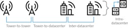
One remaining part of the network where high-frequency traders can trim latency is the last-mile connection between the microwave tower and the datacenter hosting the trades and intra-datacenter connections. It is here that low-latency hollow-core fiber trounces glass fiber (see Fig. 1). Hollow-core fiber is ideal here because these links are typically shorter than a few kilometers, the data rates are 1 to 10 Gbit/s, and the signals are transmitted via intensity modulation and received via direction detection.
OFS’s photonic bandgap fiber
OFS (Somerset, NJ) introduced a photonic bandgap fiber1 with unique features (see Fig. 2). The fiber uses a relatively large air core encapsulated by an array of smaller hexagonal cells that run along the length of the fiber. The cladding also has six large holes—a unique feature—that surround the core. These are “shunts” and their role is explained below.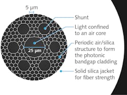
The hollow-core fiber operates as follows: The cladding confines the light to the air-core along the length of the fiber, as with a solid-core fiber. The periodic air-glass cladding prohibits light from penetrating into the cladding due to the photonic bandgap effect.
At some discrete wavelengths, though, such light that is confined to the fiber can be guided not only within the core, but also in the many glass features around the core and in the cladding. Due to the inevitable microscopic roughness of the air-glass interfaces in the fiber, a small fraction of this light keeps being reflected at random angles while it propagates along the fiber, creating narrow spectral regions of high optical loss. So, the transmission spectrum of the hollow-core fiber is characterized by windows of low loss separated by high loss at certain wavelengths (see Fig. 3). This contrasts with traditional optical fibers that enable transmission over a wide continuous range of wavelengths.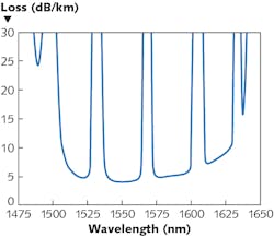
Modes, core, and shunts
The photonic bandgap fiber has a relatively large core—25 μm in diameter (see Fig. 2)—that provides freedom in how light is distributed so that multiple modes can guide. As mentioned above, the dominant loss mechanism in a hollow-core fiber is scattering at the air-glass interfaces. The fiber loss can be reduced by increasing the core diameter, which has the effect of limiting the amount of light at these interfaces.
The disadvantage of multimode transmission is that each mode of light travels at a different speed. The digital information carried by the light doesn’t arrive all at once, but is spread over time, making data recovery harder at the optical receiver.
Higher-order modes have another undesirable effect in that small imperfections in the fiber and disturbances—such as pressure on the fiber due to compression or bending—can cause the modes to couple and exchange energy with each other. This coupling creates an echo of the original signal. Such interactions are known as multipath interference and complicate the data recovery, as the echoes are effectively noise added to the signal. More significantly, multipath interference hinders the working of the fiber cable, as explained below.
OFS has solved the issue of multipath interference by embedding the shunts in the cladding. The shunts deliberately perturb the cladding’s periodic structure to increase significantly the loss experienced by the higher-order modes. The shunts act as an optical filter, stripping out the light in higher-order modes so that the fiber is effectively single-mode.
Optical fiber cabling
This fiber exhibits an approximately 30% lower latency when compared to a conventional solid-core fiber, but for a high-frequency trader to realize this benefit, an optical cable package is required to deploy the fiber. And, cabling this fiber has proven to be as complicated as designing it because cabling changes the fiber’s behavior to a degree such that the fiber may not even work.
To understand why this occurs, it is important to realize that hollow-core fiber behaves differently when wrapped on a spool than when it is cabled. Fiber on a spool is wrapped repeatedly over itself. Such layering compresses, bends, and stretches the fiber, causing a significant disturbance. Optical fiber cable, on the other hand, is designed to protect the fiber from such external disturbances, so the amount of compression, bending, and stretching can be greatly reduced.
Spooled fiber experiences such a strong disturbance that the higher-order modes are actually stripped out of the fiber before they have a chance to accumulate a significant time delay. As a consequence, modal interference is not significant in a spooled fiber as it is in a cabled fiber, where the reduced disturbances lower the loss of the higher-order modes and thus increase the impact of their more significantly delayed contributions. In essence, hollow-core fiber is highly sensitive to disturbances, making practical cabling a challenge.
The ideal approach is to avoid modal interference altogether. But this isn’t possible in practice, so the next best thing is to increase the loss experienced by the higher-order modes to stop coupling from arising. This is what the shunts visible in Figure 2 provide—a pathway for the higher-order modes to leak out of the fiber even when protected in a cable. The fiber attenuates the higher-order modes such that multiple-path interference is mitigated.
Termination and transmission
The hollow-core optical fiber is protected by a cable designed for indoor/outdoor operation; it has been successfully deployed and is carrying live traffic in several high-frequency trading networks. To prepare the fiber for transmission, standard LC or SC connectors are fusion-spliced to the hollow-core fiber. These connectors have a small length of solid-core fiber and are designed to be spliced to the hollow-core fiber while achieving a splice loss better than 2.5 dB.
Attenuation is the most important parameter in closing these transmission links. A 1 km cable has an assumed loss of 10 dB (5 dB/km of the fiber and 5 dB for the connectors), while a 2 km link has a 15 dB loss (10 dB for 2 km of fiber and 5 dB for the connectors). A transceiver with an output power of 0 dBm and a power budget of 20 dB means that the receiver’s sensitivity should accommodate 15 dB of cable and connector loss, while providing an ample safety margin of 7 dB for changes the fiber may experience. Note that there is sufficient margin to include wavelength-division multiplexing (WDM); this technology has been implemented.2
Next steps
These advances, matching low-latency transmission demand of high-frequency traders with the technological status of hollow-core fiber, are significant. However, these are the first steps to realizing the full potential of hollow-core fiber transmission. Solid-core fiber has set the standard for low loss—less than 0.2 dB/km, as well as a large transmission band, although only about 40 nm is routinely used. Clearly, the next steps are to continue to industrialize hollow-core fiber technology to expand its applicability to opportunities for longer lengths by including technologies like forward-error correction and the use of low-latency amplifiers.
REFERENCES
1. J. M. Fini et al., Opt. Express, 21, 6233 (2013).
2. B. Zhu et al., OFC 2020, paper Th4B.3 (2020).
Daryl Inniss is Director, New Business Development at OFS, Somerset, NJ; e-mail: [email protected]; ofsoptics.com.