SPECTRAL IMAGING/MICROSCOPY/ENDOSCOPY: Fast and efficient, image mapping spectrometry advances bioimaging
Tomasz Tkaczyk
Partly because of recent advances in camera development (for example, large-format, high-speed and spectral-range arrays), and partly because of its ability to reveal the chemical composition of objects, spectral imaging is increasingly regarded as an important tool in biological and medical imaging.
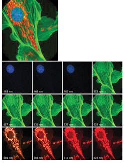
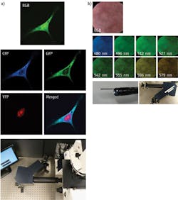
The technique can image biological samples at multiple wavelengths simultaneously (see Fig. 1). High imaging speed allows imaging fast processes for example calcium oscillations, while high spectral sampling enables imaging of similar signatures—for example, fluorescent proteins (GFP, YFP, CFP and others) separated by only few nanometers. It also allows processing of an increased number of separate spectral signatures, and therefore improved imaging throughput.
Depending on the application, spectral sampling spans from a few bands in clinical applications like monitoring of blood oxygenation to tens of bands in cell signaling1—and different applications target different spectral ranges, such as the visible range for cell signaling (fluorescence microscopy) and infrared (mid- and long-wave, or MWIR and LWIR) for gas and chemical detection in general.
Approaches and instruments
The available hyper- and multispectral instrumentation provides a variety of technological solutions to address different application requirements. The broadest categories of hyper- and multispectral imaging modalities are scanning and snapshot techniques. Scanning methods can be further split into spatial scanning (point, line, and disc scanning) and filter-based spectral scanning, with liquid crystal tunable filters (LCTFs) and acousto-optic tunable filters (AOTFs).2-4 Snapshot approaches are more diverse and include, for example, aperture splitting, aperture coding, computed tomography and image slicing.5-8
The selection of approach is critical, as it defines the acquisition speed—and thus the light budget and signal-to-noise ratio (SNR), as well as the extent of data reconstruction and processing. Scanning methods, for example, impose a tradeoff between the dwell time and spectral cube dimension (x, y, λ)—in other words, among image size, overall imaging speed, and SNR. The data in these scanning modalities is usually obtained directly and requires only modest post-processing. Similar in that regard is the non-scanning, aperture-splitting approach, which suffers significant light loss proportional to the number of applied filters. Snapshot techniques such as aperture coding and computed tomography imaging spectrometry are computationally intensive, while the majority of image-slicing methods require an extensive infrastructure for numerous spectrometers.
Scanning techniques are quite successful for applications requiring high spatial or spectral resolution while at the same time allowing a compromise in speed or signal level. In addition, in many bioimaging applications the short dwell and integration time can be at least partially compensated by increasing the power of the light source.
Most snapshot techniques, on the other hand, are still in development, awaiting a broad application opportunity. One of the most promising of these is image mapping spectrometry (IMS), which has great potential for wide implementation.9-11 To the best of my knowledge, no other snapshot technique currently available is capable of similar high light throughput (~85%) and data cube dimensions (350 × 350 × 48 x, y, λ) for real-time acquisition, analysis and display.
Image mapping spectrometry
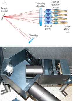
IMS works by spatially redirecting image zones to obtain space between image segments/pixels by means of a redirecting mapping mirror also called the “image mapper.” Next, by using a dispersive element, IMS obtains wavelength spread on the large format CCD or CMOS camera. Segment/pixels are grouped and imaged through the dedicated optics of a re-imaging lens array. This makes the entire system more compact and effectively applies 90–95% of a CCD/CMOS image sensor. Because IMS maps each voxel (x, y, λ) to a unique pixel of the 2-D image sensor, the entire spatial-spectral information can be acquired with no scanning in a single integration event.
No significant computation or processing is required to create the full 3-D (x, y, λ) data cube, as the data is acquired directly. Simple image re-mapping is sufficient to reconstruct the object. This way, the IMS system offers fundamental advantages in imaging speed and signal collection efficiency over current methods for spectral imaging. For example due to parallel acquisition it has a longer dwelling time comparing to scanning techniques, thus can collect more photons while still retaining a high frame rate. Direct data acquisition also allows real-time display and data analysis, avoids reconstruction artifacts, and can provide diffraction-limited performance.
IMS was initially developed for microscopy applications and the technology is currently being transitioned to the medical field—for microscopy and endoscopic cancer detection—in addition to remote sensing. Critical system components in this IMS layout are a three-segment mapping mirror, an array of dispersers and reimaging lenses, and a large-format, 16 megapixel (Mpix) CCD (Imperx; see Fig. 2).Overcoming disadvantages
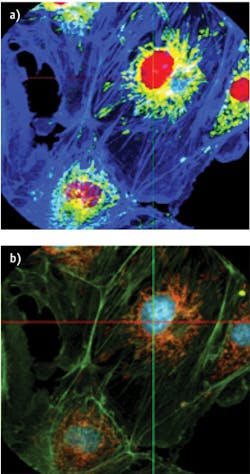
A limitation of current spectral imaging is the lack of reliable real-time feedback to the user. For example, during imaging experiments involving calcium (Ca2+), one generally plots the Ca2+ indicator dye intensity trace continuously to check for normal behavior before adding experimental perturbation. If the Ca2+ indicator dye signal is buried among other similar spectral signals, however, such monitoring becomes very difficult. Spectral unmixing allows one to separate spectrally similar dyes—though it needs to be combined with real-time data-cube measurements. IMS provides this capability; Figure 4 shows an example of unmixing done in real time. While IMS has numerous advantages, its primary constraint is that the dimension of the data cube depends on the size of the image sensor. This means that the total number of voxels cannot exceed the total number of pixels on the camera, although it is possible to increase the spatial sampling at the expense of spectral sampling, and vice-versa. So for example, a 1024×1024 pixel camera can build a data cube (x, y, λ) either in the 256 × 256 × 16 or 512 × 512 × 4 formats (the first two numbers describe spatial sampling, and the third one indicates spectral sampling). Realizing higher spatial and spectral sampling simultaneously requires a larger format camera. Large-format CCD cameras available currently have 16+ Mpix, allowing the IMS to acquire data cubes up to 500 × 500 × 64. Note, however, that currently available CCDs used in aerial photography allow acquisition of images using 60 to 250 Mpix formats, while infrared cameras allow 1 Mpix format (in both MWIR and LWIR). On the other hand, consumer-grade cameras have recently reached 85 Mpix resolutions. So it seems clear that further extension of IMS data cube dimensions will be easily implementable in the near future.The IMS technique has a great potential for biological and medical imaging. The snapshot mode and high light collection efficiency allow high SNR while reducing photobleaching effects, and is also advantageous in applications where light source compensation is impossible. Spectral range and resolution enable IMS to distinguish among multiple spectral signatures, even those that are densely packed. So, IMS presents as a powerful new modality for hyper- and multispectral applications, and as time goes on, it is likely to fill the imaging space for low signal applications, rapid imaging and processing for biological imaging, medical imaging and numerous other applications.
REFERENCES
1. M.A. Rizzo and D.W. Piston, Biophys. J. 88, L14–16 (2005).
2. Carl Zeiss MicroImaging GmbH, Jena, Germany, LSM 710 product brochure, www.zeiss.com.
3. ChromoDynamics, Inc., Orlando, FL, HSi-300 hyperspectral imaging system data sheet, www.chromodynamics.net.
4. Cambridge Research and Instrumentation, Inc., Cambridge, MA, VARISPEC liquid crystal tunable filters brochure, www.cri-inc.com.
5. D.B. Duncan and G. Leeson, Proc. SPIE 3649, 100 (1999).
6. C. F. Cull et al., Appl. Opt. 49 (10), B59–B70 (2010).
7. B. Ford et al., Opt. Exp. 9 (9), 444–453 (2001).
8. F. Hénault et al., Proc. SPIE 5249, 134–145 (2004).
9. L. Gao et al., Opt. Exp. 17 (15), 12293–12308 (2009).
10. L. Gao et al., Opt. Exp. 18 (14), 14330–14344 (2010).
11. R.T. Kester et al., J. Biomed. Opt. 16 (5), 056005 (2011).


