Spectroscopy and Optics: Laser mirrors: High reflectance is measured best with cavity ring-down spectroscopy
High-reflectance mirrors, with reflectance values ranging from 99.8% up to 99.999%, are essential components in most laser systems for beam steering while maximizing throughput. It is common industry practice to determine mirror reflectance by measuring transmission using spectrophotometry and assuming that the rest of the light was reflected. However, this false assumption does not consider scatter or absorption, leading to overly optimistic reflectance values. For mirrors with reflectance values above 99.5%, a more accurate way to determine reflectance is to measure total loss through cavity ring-down spectroscopy (CRDS). Understanding your supplier’s metrology is critical for predicting real-world performance.
In many laser applications, including medical laser systems and laser materials processing, there are typically anywhere from 2 to 12 mirrors used for beam steering. Minimal loss and high reflectance values of these mirrors are crucial for maximizing throughput and avoiding system damage, especially when many mirrors are used. Dielectric coatings are typically used to maximize the reflectance and laser-induced damage threshold (LIDT) across a small bandwidth, with typical values for reflectance and LIDT of >99.5% and >20 J/cm2 for 20 ns, 1064 nm pulses. However, for particularly sensitive applications where maximizing throughput is especially important, reflectance values up to 99.999% may be required. These ultrahigh-reflectance mirror coatings are often deposited through tightly controlled processes such as ion-beam sputtering (IBS).
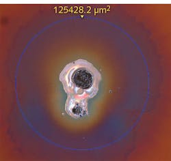
Any light not reflected will be either transmitted through the system, absorbed, or scattered. Undesired transmission can lead to a beam focusing somewhere else in the system, which may lead to safety issues or laser-induced damage. Absorption is even more likely to lead to laser-induced damage through thermal effects (see Fig. 1). Although scattered light is less focused and intense than the original beam, it can reduce throughput, introduce noise into the system, and potentially lead to damage when using high-power lasers. Unwanted transmission, absorption, and scatter not only impact the final performance of reflective optical components, but they also affect optical suppliers’ ability to determine if the desired reflectance is being met.
Standard method of measuring reflectance
Because laser mirrors have such demanding reflectance requirements, verifying that mirrors meet their intended reflectance is critical for guaranteeing real-world performance. However, the standard way optical component suppliers verify mirror reflectance is rooted in a false assumption: that a transmission measurement is sufficient for determining reflectance. ISO 15368:2001 outlines quantifying reflectance using spectrophotometers to directly measure transmission. However, spectrophotometry cannot determine if absorption or scatter are present, and both of these processes may significantly impact system performance when very high reflectance values are required.
This industry-standard method of basing reflectance values on transmission measurements assumes that scatter and absorption are insignificant, leading to the false assumption that the sum of all present intensities is given by reflection and transmission. However, scatter and absorption are often significant and must not be ignored when dealing with precise laser systems.
Direct measurements of reflectance with a spectrophotometer typically have an uncertainty of ±0.5%. With extreme care, this can be reduced to ±0.1%, but this is still not accurate enough for mirrors with reflectance higher than 99.5%, where the difference between passing and failing can be <0.1%. Because directly measuring transmission and inferring reflectance is not accurate enough for high-reflectance optics, another solution is required.
Ace in the hole: cavity ring-down spectroscopy
Cavity ring-down spectroscopy (CRDS) provides an ideal solution for determining the reflectance of highly reflective optics by measuring the total loss of the optic, which includes absorption, transmission, and scatter. The reflectance of the optic can then be determined by subtracting the measured loss from 100%.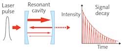
In CRDS, a resonant cavity is formed by two highly reflective mirrors with reflectance values of around 99.99%. A laser pulse is then sent into the cavity where it oscillates between the mirrors, losing a small amount of intensity at each reflection due to transmission, absorption, and scattering (see Fig. 2). An intensity detector is placed after one of the mirrors to record the decreasing intensity of the reflected light as a function of time. This allows the total loss of both mirrors to be determined by the decay time, or “ring down,” of the reflected light inside of the cavity.
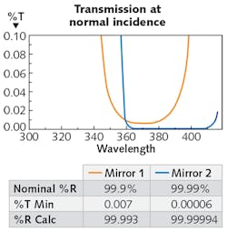
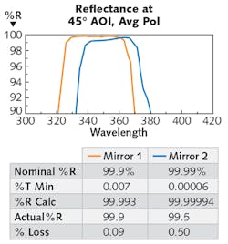
The sensitivity of directly measuring a laser mirror’s reflectance with an uncertainty of ±0.1% (left two examples) is two orders of magnitude greater than directly measuring the mirror’s loss with an uncertainty of ±10% through CRDS (right two examples), demonstrating that loss measurements are much more accurate than reflectance measurements for highly reflective optical components.
The intensity of the laser pulse inside of the resonant cavity is described by:
I(t)=I0e-Ttc/2L
I(t): Intensity of the laser pulse as a function of time
I0: initial laser pulse intensity
T: total cavity mirror loss
t: time
c: speed of light
L: length of cavity
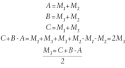
The loss value measured in a CRDS system is the loss of both mirrors in the cavity. Therefore, three tests must be performed using reference mirrors to determine the loss of one unknown mirror. Two known reference mirrors are used to form the resonant cavity for an initial calibration measurement (A), and then two more measurements are taken with the unknown test mirror replacing each one of the reference mirrors. Consider the measurement done with the first reference mirror replaced by the test mirror as measurement B and a measurement with the other reference mirror replaced by the test mirror as measurement C. Now, measurements A, B, and C can be used to determine the loss of the unknown test mirror by following the following set of equations where M1 and M2 are the loss of the two reference mirrors and M3 is the loss of the test mirror:
Cleanliness is critical to accuracy with a CRDS; any dust inside the instrument cavity or contamination on the mirror surfaces will result in an increased loss and reduced reflectance. Consequently, CRDS systems are normally operated in a clean room. The direct measurement of loss in CRDS is ideal for characterizing highly reflective laser optics because it is much easier to accurately measure a small amount of loss than a large reflectance value. The reflectance values of test components will be around 99.9% to 99.999%, requiring that the uncertainty be <0.001% of the total reflectance (or a sensitivity of 1 × 10⁻⁵). As previously mentioned, direct measurements of reflectance can only achieve an accuracy of around 0.1% (1 × 10⁻³ sensitivity). On the other hand, if the total loss of the components is measured, this is an extremely small quantity of 0.1% to 0.001% (or 1000 to 10 ppm) and it only needs to be known to within 5% to 10% of the total loss.
Real-world examples
The table provides an example of this by showing the resulting sensitivities of measuring two unknown test mirrors through either direct-reflectance measurement or direct-loss measurement to see which mirror has a higher reflectance. Using the direct-reflectance technique, the measured values of the mirrors are essentially identical due to the low sensitivity of the measurement, making it impossible to distinguish which mirror has a higher reflectance. However, direct-loss measurement through CRDS clearly shows that the second mirror has a higher reflectance.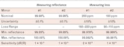
Key takeaways
While reflectance may seem like a rather simple specification, it is actually a difficult value to measure for highly reflective optics such as laser mirrors. The best technique for reflectance characterization is dependent on the application requirements and reflectance level of the component. Cavity ring-down spectroscopy (CRDS) calculates high reflectance values by directly measuring the total loss from absorption, transmission, and scatter, and is ideal for quantifying high reflectance values above 99.5%. However, CRDS cannot determine reflectance values below 99.5%, and direct-reflectance measurements through reflection spectrophotometry should be used in these cases. Truly understanding the way that your highly reflective optics have been measured is imperative for predicting how they will perform in your application.
About the Author
Ian Stevenson
Principal Engineer, Edmund Optics
Ian Stevenson is principal engineer at Edmund Optics (Barrington, NJ).

Cory Boone
Cory Boone is technical marketing manager at Edmund Optics. He is responsible for managing the creation of technical marketing content, including application notes, published articles, web copy, email campaigns, video scripts, trade show materials, case studies, and other marketing literature. He plans the company’s technical content strategy and acts as the technical voice of the marketing department. Cory is also active in educational outreach and spreading general awareness of the optics industry. He received a B.S. in Optical Sciences and Engineering along with minors in Math and Material Science Engineering from the University of Arizona.