Nanopositioning: Piezo nanopositioners are at the core of nanoscale instrument design
JENICE A. CON FOO
The need for nanoscale-resolution instrumentation spans a range of applications as diverse as materials science, life sciences, and astronomy. Nanoscale instrument design begins and ends with the judicious choices of the nanopositioner. This article describes the characteristics of nanopositioners and their application to nanoscale instruments.
What is a nanopositioning system?
A typical high-resolution nanopositioning system comprises a flexure-guided stage that is actuated with ceramic piezoelectric actuators and a position sensor. Flexure hinges are ideal for subnanometer positioning because no two parts in contact move relative to each other. The flexure hinges ensure smooth, repeatable, and frictionless motion with the capability for extremely small movements. The flexure design determines many of the final nanopositioning system characteristics, such as range of motion, response, and repeatability.
Under an applied electric field, a piezoelectric actuator changes in length, yielding displacements of up to several hundred micrometers for an applied voltage of approximately 150 V. The displacement of the piezoactuator is small, but the step resolution is often better than a fraction of a nanometer. Unfortunately, piezoactuators exhibit both creep and hysteresis, but this can be compensated by a position sensor and closed-loop feedback control. The position sensor must be able to resolve displacement over a range of hundreds of micrometers down to picometers.
How to choose the correct nanopositioner
The position of a nanopositioner within its range of motion is proportional to the commanded input voltage, and the overall range can be very different according to the design of the positioning system. As a result, the design choice for range of motion directly affects the minimum step size achievable. For example, a stage with a 100 μm range, when commanded using a 16-bit digital-to-analog converter (DAC), has a minimum step size of approximately 1.6 nm.
Based on the application, users need to make the appropriate compromise between minimum step size and range of motion. For many optical applications, a 1.6 nm step size is smaller than necessary—however, for atomic-force microscopy (AFM), an even smaller step size is required. To meet this demand, the range of motion could be reduced to 25 μm, yielding a minimum step size of 0.4 nm. The step size could be further reduced by using a 20-bit DAC.
The next consideration is speed. Most positioning applications can be characterized as requiring either continuous scanning motion or step-and-settle motion. An example of the former is raster scanning, which is commonly used for inspection. Examples of step-and-settle motion include interferometry and beam steering, where it is more important to steer to a chosen location and then allow the closed-loop feedback control to maintain that position.
Although range of motion influences the achievable speed of the nanopositioner, its stage flexure design has the largest effect. In general, nanopositioning stages with high resonant frequency produce faster responses. However, the tradeoff may be reduced range of motion or reduced load capacity.
Finally, position-sensor performance is a major consideration when choosing a nanopositioner. When combined with the controller electronics, the sensor determines the achievable resolution limit of the system. Mad City Labs measures the position noise as a function of frequency of all nanopositioning systems. This measurement gives information on not only the minimum noise floor, but also on the time dependency of the position noise, which is critical for long-time-period applications. When choosing a nanopositioner, users should always ask to see the noise power spectrum.1
Mad City Labs' nanopositioning systems have been used in a variety of applications, including interferometry, AFM, and advanced fluorescence microscopy.
High-resolution steps with long-term stability
The low-noise performance and high-resolution capabilities of an angular nanopositioning system (Nano-MTA2) were tested in the laboratory of Marco Pisani, a researcher at Isituto Nazionale di Recerca Metrologica (Torino, Italy).2 This two-axis, tip/tilt closed-loop nanopositioner has a total range of motion per axis of 2 mrad. The measurement principle used in the experiment combines the effect of the optical lever and the reflection law in a multiple-reflection setup.
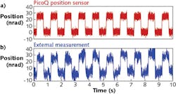
The nanopositioning system is commanded with a 25 nrad peak-to-peak square wave at 1 Hz frequency using the internal 20-bit DAC (see Fig. 1). The position is measured by two methods: output voltage from the PicoQ position sensor, and the external angular-displacement measurement described above. To put this measurement into perspective, a nanoradian is the angle formed by a micrometer-high object a kilometer away. The sensor output of the sensor is an analog voltage signal available from the front panel of the Nano-Drive controller.
Figure 1 shows that the results of the external angular measurement (blue) correlate closely with the data obtained from the sensor output (red). These data demonstrate the capability to take extremely small steps of 25 nrad using the Nano-MTA2 nanopositioner and for these steps to be discerned by an external measurement. The nanopositioner has been widely used for interferometric applications, including in the Advanced Laser Interferometer Gravitational-Wave Observatory (LIGO) optical subsystem, which called for extreme step resolution and long-term stable performance.
Atomic steps on silicon
A homemade AFM using a three-axis nanopositioner for the probe positioner achieved atomic step resolution, showing the suitability of closed-loop nanopositioning systems for metrology applications.3 Silicon (111) has a stated monatomic layer thickness of 0.312 nm. Using such a well-known and well-defined physical sample allows for accurate characterization of the AFM's accuracy and resolution, and therefore the accuracy and resolution of the nanopositioning system that is part of the AFM. This silicon substrate has been previously confirmed to be an excellent AFM calibration sample.4
The demonstrated low-noise properties of piezo nanopositioning systems allow for precise surface height measurement at the picometer scale when used as part of an AFM instrument. A lateral x-y scan of the sample with simultaneous z-axis position sensor measurements yields the topographic structure of the sample.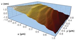
The resulting data shown in Fig. 2 clearly demonstrate that the individual atomic layers can be resolved using the Nano-HS3 nanopositioning system. Each color shift in the image represents a different atomic layer measurement. Based on these measurements, the average step height was calculated as 311 pm with a standard deviation of 3 pm. Ndubuisi George Orgi and colleagues at the National Institute of Standards and Technology (NIST; Gaithersburg, MD) derived an accepted value of 312 ± 12 pm.5These data externally verify the position resolution and low noise of Mad City Labs' nanopositioners in a relevant, real-world application. The data also verify the accuracy of PicoQ sensor technology, which were independently calibrated using NIST-traceable interferometry.
REFERENCES
1. J. F. MacKay, "Understanding noise at the nanometer scale," Laser Focus World (Mar. 2007); https://goo.gl/NF3eP8.
2. M. Pisani and M. Astrua, Appl. Opt., 45, 1725–1729 (2006); https://doi.org/10.1364/ao.45.001725.
3. J. F. MacKay et al., "Piezoelectric nanopositioners forge low-cost atomic force microscope," Laser Focus World (Oct. 2011); https://goo.gl/A885ND.
4. M. Suzuki et al., J. Vac. Sci. Technol. A, 14, 1228 (1996).
5. N. G. Orji, R. G. Dixson, J. Fu, and T. V. Vorburger, Wear, 257, 12, 1264–1269 (2004).
Jenice A. Con Foo, Ph.D., is a member of the sales and marketing group at Mad City Labs, Madison, WI; e-mail: [email protected]; www.madcitylabs.com.