Materials-processing Modeling: Dynamic Spot Shaper software improves laser heat treatment
JESÚS DOMÍNGUEZ, M. ANGELES MONTEALEGRE, JUAN F. IZASA P., and PAULA SANCHO
One of the major challenges in laser hardening of metals has to deal with geometrical irregularities of the treated components. This problem arises particularly in laser hardening of uneven surfaces such as those with sharp edges or holes. In these cases, because of the differences in the surrounding volume of the material, overheating problems often appear, leading to unacceptable treatment results. Despite numerous efforts to figure out how to achieve uniform transformation profiles, the design and control of a beam-delivery strategy that leads to a desired transformation profile in the general case remains a technical challenge.
One problem is that the width of the heated zone is limited by the dimensions of the focused laser spot. One solution is to use optics to modify the shape of the spot—for example, to create a substantially rectangular spot having a more-or-less uniform energy-density distribution.
As an alternative, scanning optics can be used to repetitively move the spot over the track so that the heat source can be considered a rectangular source moving along the track. The use of scanning optics allows adapting the distributions of the laser power density in a determined area by changing the laser trajectory and by varying parameters such as the scanning speed and/or laser power inside this area.
Dynamic spot-shaper software
Dynamic Spot Shaper (DSS) is the name given to novel control software developed by Talens Systems. The following equation summarizes the relationship between the main process parameters that participate in laser processes and that, among others, are taken into account in the DSS software:
E = P/(Ø · V)
where E (J/mm2) is the energy deposited per unit area, P (W) is the laser power, Ø (mm) is the spot diameter, and V (mm/s) is the scanning speed.
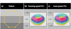
Tailoring and adapting the shape of the customized 2D beam to provide enhanced heating of the surface can be initiated and controlled by the DSS software in two ways. The most intuitive way of changing the energy-density distribution within the effective spot is to modulate the laser power within the scanned pattern, requiring a quickly modulated laser source. The second, and preferred, way is to change the time during which each segment of the customized spot is heated up by scanning the pattern at different speeds.
Figure 1 shows, for a given pattern, the 2D customized beam generated by use of these two techniques—varying the scanning speed and varying the laser power. It can be observed that the 2D beam generated is the same in both cases. The table shows the range of powers and scanning speeds used to achieve these two equivalent beams.
The combination of the scanner and the DSS software is what provides the ability to dynamically adapt the laser beam shape in real time to geometrical singularities.
Laser-hardened crankshafts
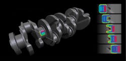
The combustion-engine crankshaft is one of the most challenging parts to successfully laser-harden because of its lubricant holes, differing and complex geometries, and the demanding mechanical requirements of the part itself. Hardening these complex geometries is possible using DSS via customizing the laser beam both in shape and in energy-density distribution.
Figure 3 shows two different cross-sections of treated areas—the result of band hardening, and band and fillet hardening with controlled depth along the hardened zone. One of the main challenges of journal laser hardening is the lubrication holes placed along the laser track. Without appropriate control of the process, overheating of the surrounding areas is likely, melting the edges of the holes. The dynamic beam shape generated by varying the energy distribution within the pattern using DSS can harden around the hole with no negative impact on the metallurgical properties of the part. The software is currently integrated in production lines for laser hardening of crankshafts with a delivery time of 180 s per piece.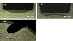
In addition to laser hardening, the DSS software can be used in other laser applications such as cladding, welding, and remelting, as well as for other industrial sectors that include automotive, aerospace, and mold-and-die manufacturing.
Jesús Domínguez, M. Angeles Montealegre, Juan F. Izasa P., and Paula Sancho are all with Talens Systems, ETXE-TAR Group, Elgoibar-Guipúzcoa, Spain; e-mail: [email protected]; www.talenssys.com.