Scanners: Three-axis laser scanning technology improves demanding materials processing applications
MUSTAFA COSKUN
As the number of large area, web-fed, and remote laser material processing applications grow exponentially, applications such as cutting, engraving, texturing, and laser additive manufacturing are becoming increasingly demanding. A diverse number of commercially available lasers have been developed to serve these demanding applications that optimize specific processes on specific materials. Development of advanced beam delivery systems such as galvanometer-based laser scanners are also focusing on these demanding applications.
Three-axis Lightning-II (LII) galvo-based laser scanning systems from Cambridge Technology (CTI) combine two technologies to serve these applications: three-axis post-objective scanning and LII all-digital scanning. With higher throughputs, higher accuracies, and the ability to perform laser operations over larger field sizes, three-axis LII systems enable laser processes to serve demanding applications in flat-panel display, electronics, solar, textile, automotive, and 3D printing industries.
Post-objective scanning
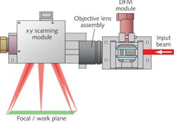
The three-axis working mechanism is commonly referred to as post-objective scanning because the scanning mirrors are located after (post) the focusing (objective) lens (see Fig. 1). Using post-objective scanning technology, scanning systems can achieve larger field sizes and smaller spot sizes, and can handle higher laser power levels. In this architecture, the raw laser beam enters the optical system through a dynamic expander lens and the objective lens re-images the beam waist formed by the dynamic expander lens onto the target plane.
Moving the expander lens by using a dynamic focusing module (DFM) varies the distance of the focal plane; hence, dynamic focus. The xy scanning module folds the optical path and scans the target work plane with dedicated scanners for the x and y axes. Orchestrated by a scan controller, each xy coordinate on the work plane will have its own dynamically adjusted z coordinate that allows the user to perform industrial laser processing tasks on a flat field or within a volume.
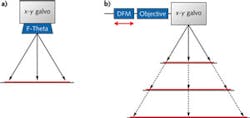
The majority of laser processing tasks are conducted on a flat surface. Traditional two-axis scanheads need special scan lenses (such as f-theta lenses) to flatten the field since an uncorrected xy galvo system results in a spherical focal field (see Fig. 2). Three-axis technology does not need a scan lens to flatten the focal field; instead, the necessary field flattening is achieved by dynamically adjusting the focal distance for each point in the work field via the DFM.Large fields of view
Three-axis scanning systems are primarily used for scanning large-field, two-dimensional (2D) surfaces where field-flattening lenses and two-axis scanheads are no longer practical. The impracticality of two-axis systems usually comes from the size, complexity, and ultimately the cost of the scan lenses for large-field applications.
In a three-axis system, by placing the focusing (objective) lens before the scanhead, the sizes of the optical elements become independent of the field size; that is, the location of the DFM with respect to the objective lens determines the nominal working (focal) distance. Since the working distance determines the field size, the longer the working distance, the larger the field size (see Fig. 3).The configurable design of three-axis technology allows large or variable field size scanning applications with a single lens set. However, as the focal distance (f) and the field size are increased, the spot size will also increase, reducing the power density (assuming constant laser power). This may not be ideal since a certain power density is necessary for an efficient laser process. Three-axis scanning solves this problem by reducing the spot size by increasing the beam diameter (D) on the focusing optics per the equation: spot size = k * m2 * λ * f / D, where k is a constant, m2 is the quality factor of the laser beam, and λ is the laser's operating wavelength.
In a traditional two-axis scanhead solution, the beam diameter is limited by the entrance pupil of the scanning lens. For large input beams (usually >30 mm), the scan lens for a two-axis scanhead becomes very large and costly. Because a three-axis system has the objective lens upstream to the scanning mirrors, the size of the required clear aperture of the focusing lens is significantly reduced. Thus, larger beam diameters can be propagated through the optical system with a cost-effective lens design in order to achieve smaller spot sizes. In other words, the increase in the spot size due to the f, which is required for large-field applications can be compensated for by the large D on the focusing optics to deliver the optimal power density for the laser process.
Higher throughput and accuracy
In addition to a larger field of view, emerging industrial laser processes require higher throughput from scanning systems. This can be achieved by increasing both linear scanning speed and laser power density together. For a given angular scanning speed, the linear scanning speed at the work plane can be increased by simply increasing the focal length of the three-axis system. Because increasing the focal length makes the resulting spot size larger and lowers the power density, the ideal solution is to increase the angular speed of the galvo-based scanner system so that spot size will not be compromised for speed. These challenging requirements for angular speed formed the foundation of LII scanning technology.
Using proprietary state-space modeling of the exact galvanometer dynamics, LII technology applies velocity-limited, acceleration-limited, and jerk-limited commands to drive the galvanometer to the peak of its performance under high-accuracy servo control. Pulse-width-modulated (PWM) drive outputs achieve 98% efficiency, sending the power to the galvanometer while keeping the servo electronics cool. Optimized scanning mirrors complement the galvo and servo technology. Machined from the lightest and stiffest material, beryllium, the mirrors are attached to the galvanometer using tapered mounts to create a balanced structure with seamless strength distribution at the lowest possible inertia to achieve scanning speeds of greater than 75 m/s for a 1 × 1 m field.
Another critical requirement for large-field, high-resolution and high-speed scanning applications is accuracy—both static and dynamic. To achieve extremely low drift (sub-μRad) per degree Celsius, the position detector in LII digital galvo technology integrates high-line-count, dual-encoder sensors and a thermally balanced design. In addition, the LII servo driver's 24-bit digital processing provides high positioning resolution and accuracy over large field sizes.
As part of the servo architecture, state-space modeling monitors power output to the scanner and compensate for various scanner parameters that change with temperature such as coil resistance, torque, and resonant frequencies. Whether cooling with air or an integrated water jacket for peak power capacity, the temperature compensation keeps settling accuracy consistent.
Mirror balance is also an important factor in maintaining accuracy for high-acceleration applications. Beryllium substrate mirrors are mass-balanced and designed with key features to minimize off-axis wobble and enable new balancing techniques. To complement the load balance, performance xy brackets are provided to withstand the strong opposing forces generated by the scanner's high torque. As a result, utilizing the three-axis LII technology, laser processing systems are able to achieve micron-level position accuracies even for field sizes as large as 1 × 1 m.
Next-generation galvo-based laser scanning systems are an integral part of the future of manufacturing as they enable traditional mechanical processes to be replaced by their laser-based counterparts. Three-axis LII systems specifically target large-field, high-throughput, and high-accuracy applications, improving laser-based material processing—the next phase of the industrial revolution.
Acknowledgement
Lightning-II is a trademark of Cambridge Technology.
Mustafa Coskun is a product manager at Cambridge Technology, 125 Middlesex Turnpike, Bedford, MA 01730; e-mail: [email protected]; www.cambridgetechnology.com.


