New approach improves far-field measurements
DERRICK PETERMAN and JEFF GUTTMAN
Rapid growth of the optical telecom market is creating tremendous demand for active and passive photonic components. Both the suppliers and users of these components must be able to verify the performance of these devices. Most of them—laser diodes, light-emitting diodes (LEDs), vertical-cavity surface-emitting lasers (VCSELs), waveguides, and optical fibers—emit light with large divergence angles. The characterization of divergent light sources poses several challenges, especially when testing in high volumes. Fortunately, these components can be characterized by a process that takes little time and is relatively easy to implement.
Far-field pattern—why measure it?
The far-field region exists at the distance from a source aperture where the electromagnetic wave-intensity pattern is essentially the same as the one observed at infinity. A light-intensity profile measured at a distance D away from the test source aperture of width d, which emits light at a wavelength λ, and meets the following condition:is said to be in the far field. The light intensity profile measured at a distance D that is much smaller than πd2/λ is called the near-field pattern. For simplicity, most optical measurements are obtained either in the near field or far field—and not in the intermediate field between the two.
Obtaining the irradiance pattern of a test device in the far field has several advantages over near-field measurements. For example, the angular measurement resolution of any light intensity pattern increases as the distance from the source aperture increases. This means the best angular resolution is achieved in the far field. In many cases, the improved angular resolution obtained is significant. Another advantage of far-field measurements is that none of the focusing optics and mechanical positioning otherwise required for near-field measurements is necessary.
Near-field measurement of sources only a few microns in size requires a magnifying lens to focus the near-field image onto a detector to obtain a measurement with any meaningful spatial resolution. The optical alignment required for these measurements is often prohibitive for high-throughput measurements. Consider a 10-µm single-mode bare fiber illuminated at 1550 nm. The near-field region is no farther than 20 to 40 µm from the end of the fiber. The same conditions exist for any light source with a source aperture of a few microns. Positioning and focusing requirements make it unlikely that near-field measurements can be performed at the speed required for production applications.
In addition to positioning and focusing requirements of near-field measurements, it may be highly impractical to find a suitable lens to focus the output light onto a detector for a near-field measurement. This is especially true for highly divergent sources, when the required lens must have a large numerical aperture (NA). At telecommunications wavelengths, highly divergent sources with NAs of greater than 0.50 require lenses that are expensive and may not focus the image properly, causing distortions.
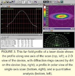
Near-field measurements are rarely used to characterize devices in high volumes because of the mechanical positioning and optical gymnastics required for small, divergent light sources. Instead, far-field measurements are used. Device characteristics obtained in the far field include the divergence angle of the light; chip pointing and alignment in a package; structures and defects; single-mode or multimode device operation; ellipticity of the light pattern; as well as the mode-field diameter, effective area, and NA of optical fibers.
Far-field measurement issues
While far-field measurements provide a great deal of information about divergent light sources, there are still obstacles to overcome. The most obvious difficulty is that the far-field pattern of divergent sources spreads out such that no single, stationary photodetector can capture the entire profile. For this reason, it is common to mount a detector on a moving stage, and move the detector around to generate the far-field pattern. Alternatively, the detector is held fixed and the source is moved. The major drawback to this technique is that obtaining the far-field pattern is time consuming, with the analysis often taking several minutes, or even hours.
Another far-field measurement technique is based on a system of lenses that focuses the far-field pattern onto either a charge-coupled device (CCD) or vidicon sensor. However, there are several drawbacks to this method. The test device must be positioned very accurately in the focus of the lens system or the results degrade significantly. The additional time and expense for this positioning can be substantial, depending on the device and application. While reasonable angular resolution can be obtained using CCD cameras with silicon as the sensor material (approximately 0.2° to 0.5°), at telecom wavelengths, comparable angular resolution is significantly more difficult to obtain with CCD arrays or vidicon sensors. It is worth noting that CCD sensors are often quite small and provide a limited field of view. In addition, attenuators or filters are usually required with vidicon and CCD sensors, adding additional distortion to the data. Vidicon sensors are also prone to problems—such as image persistence and nonuniform responsivity—that affect the data.
Even if issues involving the sensor are overcome, there are limitations whenever a lens is used to image the profile. Due to the NA available for the focusing optics, it is difficult to measure half angular divergences of greater than approximately 45° at visible wavelengths. At telecommunications wavelengths, the limitation is even more extreme—with 28° the typical divergence limit. Many active and passive telecommunication devices transmit light of well over 30° of divergence. In general, using a focusing lens system to project the far-field image onto a sensor is limited in accuracy, measurement speed, and range of analysis.
A new approach
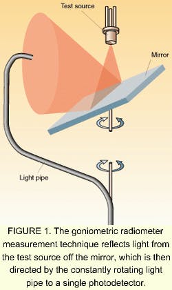
To overcome existing limitations in far-field measurement, Photon developed an instrument designed to quickly measure far-field irradiance patterns with a high degree of precision. The instrument acquires far-field irradiance patterns with a mirror and rotating light pipe (see Fig. 1, top of this page). This process keeps both the light source and the photodetector fixed, thereby eliminating the time-consuming processes required to control the position of either the source or detector.
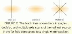
The technique requires relatively little precision in positioning the test light source and does not use a lens or attenuator that could introduce distortions into the profile. A mirror reflects the light from the test source, while a stepper motor controls the rotation of the mirror. Reflected light from the mirror is routed to a fixed photodetector by a continuously rotating light pipe. The angular position of the mirror is kept stationary as the rotating light pipe directs light to the photodetector to generate a far-field angular scan along an axis in the plane of the light source aperture. Once this linear scan is completed, the mirror is rotated to the next angular position in the plane of the test source aperture to generate a new far-field scan. Both the test source and the photodetector are fixed, so the far-field scan is generated rapidly. A high degree of angular resolution, 0.055°, is achieved in each scan for a given mirror position (see Fig. 2).For detailed optical measurements, sample position is often critical. However, careful analysis has shown that the position of the test source must be accurate to only about 1 mm to accurately measure the angular width of the source to within 1%. Straightforward mechanical fixtures easily exceed this precision.
The instrument makes fast, accurate measurements of the far-field profile, and requires simple positioning of the test source without intervening optics. While previous techniques characterized these components to a certain degree, this new development allows component suppliers and users to achieve a higher level of product quality while minimizing waste due to defective components.
Derrick Peterman and Jeff Guttman are with Photon Inc., 6860 Santa Teresa Boulevard, San Jose, CA 95119; e-mail: [email protected].


