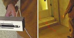
Hand-held laser tool assists the blind
For the approximately one million legally blind and estimated 200,000 totally blind individuals in the United States, the importance of improved tactile and visual tools to enable mobility is paramount. For more than 30 years, the blind have had access to commercially available electronic travel aids (ETAs) such as ultrasound sensors and other sonic-related guides. Another family of “sonification” devices aim to encode complex geometrical and topological information into acoustic or tactile stimuli; however, these devices are not practical as mobility aids because of reduced spatial resolution and the difficulty in interpreting the sonified three-dimensional data.
By considering only one-dimensional data from a hand-held noncontact device incorporating a laser and camera, researchers in the Department of Computer Engineering at the University of California (UCSC; Santa Cruz, CA) are using techniques developed in the robotic field for the analysis of range data from a rotating light-detection-and-ranging (lidar) instrument to develop a more compact and economical “virtual white cane.”1
Because lidar, used extensively and successfully for robotic navigation, is too expensive and bulky for this application, the research team used a class II HeNe pointing laser and a matrix CCD camera with 1024 × 768 pixels and a frame rate of 15 frames/s for the virtual-cane prototype system. The estimated range of the sensor is between 0.5 and 4 m, with a resolution of a few centimeters at the maximum distance.
In the detection scheme, an epipolar line is defined by the intersection of the image plane with the plane identified by the laser beam and the focal center of the system (epipolar plane). Because the position of the epipolar line is very sensitive to mechanical misalignment of laser and camera, the team implemented a simple self-calibration procedure that determines the epipolar line every time the system is turned on; the procedure takes only a few seconds as the user moves the system around to take measurements at different distances.
Detecting steps and curbs
To use the system, the laser pointer is pivoted vertically around a horizontal axis coincident with one’s wrist at a slow angular velocity (approximately 7°/s), a movement similar to that of a rotating lidar (see figure). The brightness profile of the image reflected by a planar surface is modeled by a Gaussian function. Through a series of mathematical equations and using an extended Kalman filter, the detection of features important to safe ambulation such as curbs, steps, and dropoffs can be computed and relayed to the user through audible signals (a tactile interface is planned).
In the prototype, light compensation and laser-spot detection are performed by a 2-GHz laptop connected to the camera. Range measurements are produced at a frame rate low enough that the calculations use only a fraction of the computer’s processor time. To make the system portable, the team is considering the use of a PDA for computations in the future, and may consider the use of a more economical laser line projector and linear detector rather than the laser pointer/CCD scheme.
“We are in the process of testing the prototype device with blind subjects, collecting precious feedback that will be used to improve on the current design, says researcher Roberto Manduchi. “Our hope is that this will lead to an affordable, reliable, and well-accepted tool, at which point we will consider commercialization.”
REFERENCE
1. D. Yuan and R. Manduchi, IEEE Workshop on Real-Time 3-D Sensors and Their Use, Washington, D.C. (June 2004).
