Laser ranging takes on industrial applications
Johnny Berg
In the 1970s, as US industry sought to increase productivity through the use of newly evolving technologies such as robots, it became obvious that advances in areas such as vision, tactile sensing, programmable parts feeders, and machine intelligence would be required for robotic systems to attain "generalist" capabilities. Early vision systems were almost exclusively two-dimensional (2-D) devices that could only "see" the projection of the part or object being viewed. This limited recognition capabilities as objects were rotated or turned and also required considerable control of the viewing environment.
To properly support three-dimensional (3-D) robotic movements and operations, metric information concerning the 3-D properties of the scene being viewed as well as objects in the scene was needed. This triggered a flurry of R&D efforts aimed at advanced 3-D vision-system capabilities during the 1970s and 1980s.
The earliest 3-D sensors used structured light, stereovision, and similar techniques. Their limitations included the need to control object orientation with respect to the sensor, as well as computationally complex and time-consuming image processing.
Later, direct ranging systems became available with the potential for meeting the generalist requirements needed to support advanced manufacturing. The three most common types of direct ranging systems were based on time-of-flight (pulsed systems), triangulation, and phase-comparison ranging techniques.
Direct-ranging systems
Time-of-flight systems are best suited to long-distance applications. They are also attractive for very precise range measurements (a few micrometers ranging accuracy) when heterodyne or homodyne detection is used. Their major drawback, though, is that, with pulse rates limited to tens of kilohertz, the frame times are comparatively long. Other problems such as relatively heavy configurations and high price tags limit their application.
The triangulation approach (using, for example, a CCD array and laser spot) is also very precise. But again, data-acquisition times are very lengthy if detailed mapping of a 3-D surface is required. Further, the viewing geometries and conditions must be tightly controlled.
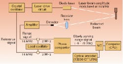
FIGURE 1. Laser-based three-dimensional (3-D) scanning sensors have become viable for commercial use. A patented scanning process provides a set of data points representing 3-D surface features. A dedicated computer stores data and processes the 3-D imagery.
For short ranges (less than 100 ft), the phase-comparison ranging technique is better at meeting the generalist requirements. Useful measurements can be made easily with phase comparisontarget-to-sensor range can be as short as 1 ft or as great as 50 ft. This range interval is important for applications such as manufacturing, robotics, and materials handling. Data rates greater than 500,000 measurements per second are achieved routinely. An object or scene can be scanned in just 2-3 s. And, at the end of the scan process, the 3-D spatial and dimensional information is available, permitting immediate application-specific processing. In addition, viewing geometries and conditions are not constrained, and direct ranging sensors work equally well in daylight or total darkness. They "see" only the laser wavelength. Object identification can be accomplished at probabilities of correct identification greater than 0.99.
Troublesome ambiguity
The technological advantages of phase-comparison ranging systems are due mainly to the availability of diode lasers. Commercially viable systems have not been available until recently because of difficulty in controlling the "ambiguity interval" of the systems. Diode lasers can be amplitude-modulated at gigahertz rates, which set the ambiguity interval, defined as the point at which the phase angle difference (W) between the reference and range signals goes through 2pi radians. The range voltage output from the phase detector can be described as
V(rng) = A(ref) A(rng) Cos [Omega]
where A(ref) is amplitude of reference signal and A(rng) is amplitude of range signal.
For these systems to be commercially useful, V(rng) must be allowed to vary only as a function of Omega. In practice, this doesn't happen. In fact, variations in the A(rng) signal can be as large as 10,000 due to variations in range, angle of incidence, and reflectivity. These variations result in large range-measurement errors. The successful solution to this problem consists of a complex combination of optical design, optical and electronic components, and electronic design.
Scanning laser radar
A 3-D vision system that applies this solution to achieve a generalist capability for a wide range of applications is scanning laser radar (US pat. #5,831,719, Nov. 3, 1998, and #5,940,170, Aug. 17, 1999; other patents pending). A diode-laser beam is rapidly and precisely moved across the scene of interest, and the distance between sensor and points in the scene is measured and stored (see Fig. 1). The scanning process (>500,000 range measurements per second) results in a set of data points representing the 3-D surface features of scene objects. The image data points are passed to a dedicated computer that stores and processes the information to produce 3-D imagery.
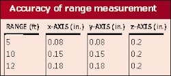
The heart of the system is a crystal oscillator. The signal generated by the crystal modulates the laser output intensity, as well as serving as the reference signal for the range-measurement process. A fraction of the scanning laser beam is reflected back to a silicon detector in the receiver channel. The output signal from the detector is compared with the reference signal. The phase difference between these two signals is proportional to range. A 3-D image is constructed from the individual range values and stored in a raster format. The accuracy of an individual range measurement is about 0.1 in. in all three coordinate axes (see table).
Practical application
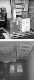
FIGURE 2. Digitized photograph of four boxes on a pallet in a typical air-cargo application depicts a desk at the left center of the picture, an aluminum ladder in the upper right, and a metal rollup door on the right (top). In a 3-D image of the same scene, the pallet is just discernable under the boxes (bottom).
A typical air-cargo application might entail localization of boxes on a pallet (see Fig. 2). In our example, the top of the pallet is located 12 ft below a ceiling-mounted 3-D sensor. This is the desired operational configuration because having the sensor out of the way permits 360° access to the boxes by a forklift. The 3-D image is comprised of about 640,000 range points acquired in less than 2 s. Each point in the image (pixel or voxel) is the range from the scanner to that point. The range values were converted to shades of gray and displayed on a digital video screen.
The lighter shades of gray are closer to the sensor than the darker shades of gray. The image also shows a rollup door, an aluminum ladder, and a desk in the vicinity of the pallet and boxes. The system displays range information across the top of the boxes and pallet, demonstrating a measurement accuracy of about 0.2 in. Once the image has been captured and placed in memory, specific processing is undertaken to determine the volume of cargo items located on the surface of the scale.
This software is written using C++ in the Windows environment. The configuration allows the operator to set specific system parameters during installation or when viewing change in geometries. The software is operator friendly and requires very little training.
JOHNNY BERG is the president of Holometrics Inc., 344 State Place, Escondido, CA 92029; e-mail: [email protected].


