Surface Characterization: Novel technologies go beyond color to measure surface appearance
HUBERT KOSTAL AND RON RYKOWSKI
An innovative combination of optics and imaging based on imaging-sphere technology delivers the ability to rapidly gauge surface appearance for virtually any type of material, including plastics, metals, textiles, glass, papers, painted surfaces, and even human skin (see Fig. 1). Because it captures the entire scattered-light distribution from a surface in a single exposure, the imaging sphere overcomes the disadvantages of instrumentation traditionally used for measuring surface appearance.
For optical applications, surface appearancedefined as the optical behavior, often as viewed by the human eye, of a surface when illuminatedis a critical factor in optical system design. For industrial applications, surface appearance is often highly correlated with process performance, for example, polish levels, absence of surface defects, and so on. Similarly, consumers have a high standard for the cosmetic appearance of a wide range of products, from natural goods such as foods, to manufactured items including textiles, electronic devices, and automobiles.
Surface characterization can be used to distinguish between materials, such as in a grading samples or comparing to a standard in quality control, or to ensure uniformity, such as when samples must be matched for appearance.
While human visual inspection remains the most common tool for gauging surface appearance, it is highly subjective, difficult to calibrate, and difficult to replicate from observer to observer. This imprecision makes visual inspection potentially expensive in a production environment. It is hard to apply standards consistently from inspector to inspector within a factory, and particularly difficult to uniformly apply standards to multiple vendors throughout a supply chain.
How can surface appearance be quantified? Probably the most obvious visual characteristic of a surface is its color, but two surfaces can have the same color, yet appear very different to the eyesuch as matte and glossy paints of the same color. Indeed, the other key cosmetic parameter, reflectivity as a function of illumination angle and observation angle, is just as important as color.
To quantify surface appearance, one must specify exactly how a surface reflects, scatters, and absorbs light. The bidirectional reflectance distribution function (BRDF) is the key metric for lit appearance; it specifies the spatial and spectral distribution of the light returned from a surface as a function of illumination conditions (spectral and spatial distribution, and angle of illumination). The BRDF is a normalized function, defined as the ratio of reflected to incident irradiance measured in units of inverse steradians. The BRDF of a surface with perfect Lambertian reflectance (that is, one which scatters such that its apparent brightness appears the same at all angles of view) is 1/π at all points. For surfaces that also transmitsuch as frosted glass, rear-projection screens and diffusing filmsan analogous function to BRDF is the bidirectional transmittance distribution function (BTDF). These two metrics can be combined into a general description of scatter, the bidirectional scatter function.
Traditional instrumentation
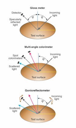
Several instruments have been used for measuring surface appearance, the most common of which are the gloss meter, the multi-angle colorimeter, and the gonioreflectometer (also known as a scatterometer; see Fig. 2). In addition, many instruments intended for specialized applications have been created.
A gloss meter consists of a light source to illuminate the test surface and a single photodetector that captures the specularly reflected light. Typically only a single illumination geometry (most commonly either 0° or 45° is supported). This makes the gloss meter inexpensive, simple to use, and fast. However, it also results in extremely limited data, measuring reflectance only at a single angle and direction, and only in the same plane as the illumination. Thus, it cannot provide meaningful characterization of surface appearance for all illumination or viewing conditions.
The multi-angle colorimeter uses a fixed illuminator and a series of spot colorimeter detectors placed at several locations, but all within the same plane with the illuminator. Again, the fixed geometry of this instrument makes it relatively inexpensive, simple to use, and fast. While it provides more spatial and wavelength data than the gloss meter, it does not provide sufficient data to generate a BRDF.
In contrast, a gonioreflectometer provides comprehensive measurement but at the expense of speed, complexity, and higher cost. In this instrument, a light source, a single detector, and the sample surface are mounted such that the illumination and sensor positions can be independently adjusted over an entire hemisphere (typically using motorized motion). The detector can be a simple photodiode, a colorimeter, or even an imaging camera. A gonioreflectometer can therefore be used to generate the BRDF of a surface with high accuracy and spatial resolution. However, because the system makes a sequential series of discrete readings, measurement speed is slow, especially if complete coverage over an entire hemisphere is required.
The imaging sphere
None of these prior technologies provides both comprehensive (multi-angle) data with reasonable measurement speed and operational simplicity. The imaging sphere specifically addresses this need, and enables rapid, accurate and complete characterization of BRDF and BTDF.
The two main optical components of the imaging-sphere system are an imaging colorimeter and a hemispherical measurement chamber. An imaging colorimeter is a charge-coupled-device (CCD) camera mated with calibrated color filters. Conceptually, it is like a spot colorimeter, except that the single detector is replaced with a CCD, so that luminance and color data can be obtained for up to millions of pixels simultaneously.
The measurement chamber comprises a hemisphere with a diffuse, low-reflectance coating on its inner surface, a curved secondary mirror, and a light source that is automatically movable to produce illumination angles from nearly 0° to 90°. The hemisphere is attached to a flat, nonreflecting baseplate containing a small aperture at its center. The surface to be measured is positioned at the baseplate aperture, and then illuminated. Both specular and diffuse reflections from the test surface strike the inner surface of the coated hemisphere, which functions as a curved screen capturing essentially all of the returned light. The convex mirror acts as a “fish-eye lens,” enabling the camera to image the entire inner surface of the hemisphere at once. Thus, the imaging sphere captures the entire 2π steradians of scattered and reflected light from the surface at this one illumination angle in a single exposure taking just seconds. The camera’s image sensor determines the angular resolution of the system, which is typically less than 0.5°. The entire instrument is housed in a light-tight enclosure, thus enabling its use in production environments having high levels of ambient light without building a special chamber or room. The system can also be alternatively configured so that illumination comes from underneath the test sample, thus allowing BTDF measurement of translucent and transparent materials.
The other key component of the imaging-sphere system is the computer hardware and software used to automatically control the instrument, acquire exposures, correct for the flat image, and process the data. In terms of analysis capabilities, the software enables the user to view various parameters, such as scatter, color coordinates, or tristimulus values at graphs, bitmap plots, 2-D and 3-D isoplots, histograms, and International Commission on Illumination (CIE) color charts.1
Representative applications
Because of its capabilities, the imaging sphere can address a broad range of applications, including rolled paper, gemstones, cosmetics, paints, displays, plastics, and metal finishing. Two specific examples serve to highlight how the imaging sphere can be implemented.
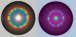
The first is the development and production of diffractive foils, now commonly used in consumer packaging and as wrapping paper. Product developers want to make the wrap visually appealing and achieve a specific visual impression. Imaging-sphere measurements enable designers to quantitatively compare various versions of a particular design. One feature enables a radar plot of the CIE color coordinates of the scattered light. This immediately gives the designer a feel for what color predominates when the foil is viewed at a given angle. This type of information would be particularly difficult to obtain with traditional, point measurement devices. The imaging sphere is also useful in the production of these foils to analyze individual units and ensure that their scatter properties conform to a target range of values. Because the imaging sphere collects scattered light from all angles at once, this can be accomplished much more quickly and accurately than by a human inspector (see Fig. 3).
Another example is the measurement of color-changing pigment characteristics. These coatings, the color of which varies depending upon the angle of view relative to the angle of illumination, are used on a variety of consumer products and automobiles. In this case, the imaging sphere enables designers to quantify the precise conditions under which the pigment will appear a particular color, and to measure the characteristics (for example, tristimulus values) of that specific color. While scattered light measurement has long been a powerful method for characterizing and quantifying surface appearance, the imaging sphere is not only faster than the eye and legacy instrumentation, it’s a versatile tool that goes beyond color.
REFERENCES
1. http://en.wikipedia.org/wiki/CIE_1931_color_space
Tell us what you think about this article. Send an e-mail to [email protected].
HUBERT KOSTAL is vice president of sales and marketing and RON RYKOWSKI is president and chief technology officer at Radiant Imaging, 15321 Main St. NE, Suite 310, Duvall, WA 98019; e-mail: [email protected]; www.radiantimaging.com.


