INTERFEROMETRY: Dynamic interferometry ensures quality of large telescope optics

In recent years the demand for meter-scale optical elements has increased significantly, driven by growth in terrestrial and satellite-based astronomy, and defense and security applications. Laser interferometry is used throughout the manufacturing of large optics to ensure conformance to demanding design specifications. More recently, “dynamic interferometry” has been implemented for vibration-insensitive measurement of large optics. The data is used to control polishing operations, verify dimensional stability of support structures, align mirror segments, and complete other critical metrology applications.
Meter-class metrology
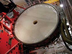
The term “meter-class” describes a category of telescopes with optical elements that are larger than one meter in diameter, typically operating within the infrared through visible spectra. The primary and secondary optics can be monolithic glass structures or can consist of multiple segments that can be actively aligned. Mirror size is only bounded by current manufacturing methods. More than a dozen telescopes are currently in operation with primary mirrors larger than eight meters, and several more challenging projects are in development (see Fig. 1).
To support new manufacturing methods, advanced metrology systems have been developed that are capable of providing quality assurance throughout the process. Laser interferometry is the most widely used technique for verifying surface quality of large optics. A laser interferometer measures the phase difference between beams reflected from a high-quality reference optic and from a test optic. In a traditional, “temporal” laser interferometer the reference optic is translated relative to the test surface in known steps, typically quarter-wavelength shifts. The instrument acquires a frame of phase data following each shift. From this phase data the optical-path difference (OPD) can be determined, and the surface shape extracted. Measurement data is compared after each polishing iteration until the final optical shape is achieved.
As the diameter of optics has grown, several issues have complicated the use of laser interferometry. Measurement times are on the order of hundreds of milliseconds so vibration can greatly affect measurement quality. Furthermore, to measure the entire optical surface, the interferometer must be positioned a significant “stand-off” distance from the test piece-in some cases tens of meters away. And turbulence within such a large cavity can significantly distort the phase data. Vibration isolation and airflow control systems on this scale can prove prohibitively expensive or functionally impractical.
Another difficulty arises when measuring space-based hardware under actual-use conditions, at extremely low pressures or cryogenic temperatures. The demanding environment combined with the extreme vibration from support equipment make such real-world testing virtually impossible with traditional interferometers.
Finally, many modern telescope designs rely upon nontraditional elements, such as conformable mirrors or aspheric optics. Characterizing these new elements creates yet another challenge for metrology systems.
Dynamic interferometry
Unlike a temporal interferometer, which acquires phase data frames over hundreds of milliseconds, a dynamic interferometer acquires all phase data simultaneously. This reduces data-acquisition time (typically to several microseconds) and enables dynamic interferometers to measure in high noise environments, without vibration isolation. As a result, the test setup is greatly simplified and the associated costs are much reduced. It also enables testing in harsh environments such as those encountered in cryogenic testing.In addition, dynamic systems can measure in the presence of significant air movement. Turbulence creates relative phase errors between the data frames in temporal measurements rendering the data incorrect or unusable. This frame-to-frame error is not present in dynamic measurement. Averaging several dynamic measurements cancels the effect of turbulence, leaving only the shape of the optic in the measurement data.
Large concave mirrors. Telescope mirror manufacturers such as the Steward Observatory Mirror Lab (Tucson, AZ) have mastered techniques for producing lightweight mirrors exceeding eight meters in diameter. Spin-casting forms the mirror’s general curvature during cooling, dramatically reducing the amount of raw material required, as well as the amount of polishing.
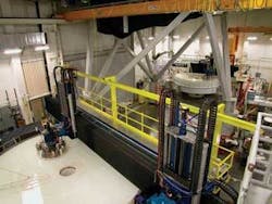
To measure large, concave mirrors, the interferometer must be positioned several stories above the mirror (see Fig. 2). Buddy Martin, project scientist at Steward Labs explains: “The path length for our measurements is typically 20 m, single pass. Even measuring in the middle of the night in an isolated test tower, with all air handlers off, vibration and turbulence limit the accuracy we can get with a temporal interferometer. With our dynamic system we’re almost immune to vibration, and can quickly take enough measurements to average out the effects of turbulence. It saves a lot of time and gives us more accurate data.”
Space hardware. Verifying the ability of space-based optics to perform to specification after deployment is critical, particularly for systems that will operate beyond the accessibility of NASA’s Space Shuttle fleet. Testing at cryogenic temperatures and low pressures is the most effective way to ensure that optical systems will perform to specification. Such testing is performed within a pressure vessel, an extremely noisy environment due to vibration from its pumps. Coupling the metrology system to the test sample and isolating both from vibration is difficult due to space constraints. It proves impossible when the test configuration requires a long measurement path.
Because of its immunity to vibration, dynamic interferometry frees manufacturers from the need to couple the instrument and test optic, and allows test configurations in which the interferometer is located inside the chamber-within its own pressure vessel-or outside the chamber, with the test beam passing through a window into the chamber. This method is often the only available option to complete these mission-critical measurements accurately and cost-effectively.
Adaptive optics. Many large telescopes now use adaptive optics on either their primary or secondary elements to counter the effects of constantly changing atmospheric conditions. The actuators for the adaptive system are typically piezo elements attached to the back of flexible elements. In the past, to understand the modal response of an optic to changes in the actuators, sensors have been used to measure movement at individual points on an optic-a slow, low-resolution solution. Dynamic interferometry, because of its short acquisition time, can image an optic as it is being actuated to verify and calibrate the response of the actuators. The dynamic system shows the 3-D response of the entire optic, providing a complete image of control system performance.
Aspherics. Aspheric optics are now used more frequently in optical subsystems to simplify designs and improve performance. To verify the performance of such a complex-shaped surface, a computer-generated hologram (CGH) is used to transform the spherical or collimated test beam into the aspheric wavefront required to test the optic.
In addition to the issues of vibration and turbulence, CGHs introduce another challenge, as test setups are very inefficient, returning less than 1% of the laser power to the interferometer. To provide sufficient power for measurement, dynamic, helium-neon-laser-based interferometers have been developed with output ranging from 7 to 15 mW (versus the 1 to 2 mW for standard instruments). These systems typically provide a beam ratio control to balance the test and reference beams and maximize contrast and measurement quality.James Webb Space Telescope
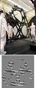
Scheduled for space deployment in 2013, the James Webb Space Telescope (JWST; see www.laserfocusworld.com/articles/277182) has presented a number of unique metrology challenges. One is the need to control dimensional stability of the primary mirror’s support structure over time, at cryogenic temperatures. To verify stability before flight, a representative test structure was built. The test plan called for three weeks of near-continuous measurement of the large, diffuse structure in a cryogenic chamber.
Electronic Speckle Pattern Interferometry (ESPI), a well-known method for measuring such diffuse surfaces, was chosen for the measurement. A dynamic phase-shifting speckle interferometer was placed outside the test chamber, several meters from the test article. The instrument simultaneously captures all phase data over the entire structure in the duration of a single 9 ns laser pulse. Out-of-plane deflections of tens of nanometers across hundreds of microns can be measured in this way (see Fig. 3).
The JWST project also required a method for verifying that the segments of the primary mirror, which are folded for launch, will align to within subwavelength tolerance upon deployment. The initial misalignment between segments is much greater than the measurement range of a standard interferometer. For this application a multiple-wavelength dynamic interferometer was used. The much longer “synthetic” wavelength generated by the instrument is capable of measuring the initial misalignment. As the segments are brought closer to alignment the wavelength is stepped down for increasing resolution.
About the Author
Mike Zecchino
Technical Communications, 4D Technology
Mike Zecchino is in technical communications at 4D Technology, Tucson, AZ.

