Displacement-measuring interferometers provide precise metrology
Semiconductor lithography has pushed displacement measurement to new limits, resulting in systems that offer high-speed angstrom-level resolution.
Since their inception in the mid-1960s, displacement-measuring interferometers (DMIs) have grown to become one of the most powerful tools for advanced position feedback. With development driven by the aggressive technology roadmap of the semiconductor lithography industry the newest generation of DMIs provide significant advantages over their predecessors.
Applications
Displacement-measuring interferometers are the primary measurement device for high-precision stage metrology in semiconductor metrology tools and lithography steppers for the production of integrated circuits (ICs) and flat-panel displays (FPDs). Original-equipment manufacturers in these industries make up a majority of the DMI market. Additional applications include characterization and calibration of machine tools, piezoelectric transducers, encoders, and grid plates to name a few.
A DMI uses the physical phenomenon of the interference of light to measure relative displacements. Precise knowledge of the wavelength of the laser light provides the fundamental accuracy of a DMI system. There are two major classifications of DMI systems: homodyne and heterodyne.
A homodyne interferometer utilizes a single-frequency laser source and tracks the deviation in amplitude that occurs as a result of a change in optical-path difference (OPD) in the interferometer. Displacement of the measurement leg of the interferometer with respect to a fixed reference results in an increase or decrease in the signal amplitude, depending on the direction of the movement. The displacement signal is monitored by a photodetector placed in the path of the interfering beams at the output of the interferometer (see Fig. 1).1
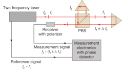
Heterodyne interferometry is a frequency-based measurement that uses phase-detection techniques to generate a measurement signal. The use of phase detection alleviates the dependency on a fixed signal amplitude to ensure system accuracy. The source in a heterodyne system is a stabilized dual-frequency laser with a fixed reference frequency (2 – 1) that is defined by the frequency split between the two polarization states. Displacement in a heterodyne system is derived from the change in phase (Δ1) that occurs with a change in optical path of the measurement leg with respect to the reference leg of an interferometer. This Doppler-shifted signal [2 – (1 ± Δf1)] is compared to the reference signal and converted into precise time-based velocity and position-displacement information (see Fig. 2).
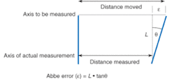
A typical DMI system consists of a laser, interferometer and beam-steering optics, measurement electronics, and a reflective target. The target, which is usually an optical-quality reflector, is located on the component that will be translated or rotated. The capability to integrate the DMI target at the plane of interest eliminates Abbe error—which results from a combination of a beam offset from the center of the translation stage and an angular error—highlighting one of the key advantages of a DMI over mechanical measurement techniques (see Fig. 3). In addition, the alignment steps for a DMI provide a square beam path (perpendicular axes) that minimizes the potential for geometrical inaccuracies such as cosine error and opposite-axis error. Cosine error results when the measurement axis is not parallel to the axis of travel; opposite-axis error is caused by a nonperpendicularity between opposing axes.
DMI developments
To address the needs of a diverse user base a DMI must provide significant flexibility. The most challenging requirements are found in a lithography IC stepper in which dynamic accuracy is typically the key attribute. Other applications have different challenges, such as minimizing the size of the stage mirror and improving a portion of the system accuracy budget. Advances in displacement interferometry have provided solutions for all of these challenging requirements.
Dynamic accuracy. In a typical IC lithography application there is a requirement to simultaneously measure from three to more than ten axes of metrology with angstrom-level resolution while the stage moves at velocities greater than 1 m/s. To achieve this requirement, synchronous measurement of all axes and precise knowledge of the electronics data age is crucial.
The data age of DMI measurement electronics has two components: a fixed latency (data age) and a variable component (data-age uncertainty). Data age is defined as the time from when the motion occurs to when the corresponding position data is latched for output from the system electronics. System control loops typically compensate for the known data age using a velocity-dependent correction term. On the other hand, the asynchronous variation of the data-age uncertainty provides a very challenging problem for control-system designers who are striving to achieve the highest level of system accuracy. For example, a stage moving at 500 mm/s that is integrated in a system whose electronics have a data-age uncertainty of 20 ns will result in a position error of 10 nm. This is a simple calculation for the position error in only one axis—the data-age error can be extreme when the variation between all axes is considered.
Integrated compensation for data-age uncertainty in DMI electronics provides the user with a method for minimizing position error resulting from data-age variation. In production, the measurement-board test and calibration procedure includes measuring the delay of the measurement and reference signals and storing the values in an on-board electrically erasable programmable read-only memory (EEPROM). During system initialization the data-age adjustment values for each axis are calculated and loaded into the hardware.2 This procedure provides the user with a resultant data-age uncertainty of less than 1 ns.
The data-age processing electronics in the measurement board also provides the ability to synchronize multiple measurement axes such that all channels read their respective displacement information within less than 1 ns of each other.
Axis handoff. The largest stage travels are typically found in the flat-panel display equipment industry in which the trend is to increase panel size. To accommodate longer travels the stage mirrors become larger, heavier, more expensive, and much more challenging to fabricate. In addition to the reluctance to pay the significant increase in price as mirrors grow in length, design engineers face the challenge of optimizing their stage dynamics to limit the effect of the higher mirror mass on stage performance.
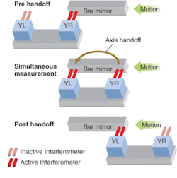
To minimize potential design challenges that result from using larger mirrors, a system-level solution has been developed that requires the use of higher-performance DMI measurement electronics to provide the capability to transfer data between interferometers. This data transfer, or axis handoff, minimizes the required mirror size by allowing the user to configure two interferometers to measure a set (or sets) of smaller mirrors mounted on the stage (see Fig. 4). The DMI axis handoff has been calibrated to an accuracy of better than 1 nm at velocities of 1 m/s.
Accuracy. The DMI is one of many contributors to a system-level error budget. In a DMI system the laser-head performance is key to ensuring that the highest accuracy can be achieved. The calculation of displacement in a DMI application is dependent on accurate knowledge of the wavelength of the laser light and is given by:
Displacement = (no. counts × wavelength)/resolution factor.
If the wavelength of the laser changes (frequency stability) it will directly affect the accuracy of the displacement measurement. For example, a 1-ppm frequency instability in a system with an optical path of more than 300 mm equals 300 nm of position error.
To qualify the frequency stability of a DMI laser, a known standard with better frequency stability, such as an iodine stabilized laser, is required. The frequency-stability calibration combines the output beam of the secondary standard (test laser) with the output beam of the primary standard (iodine laser) on the active area of a fast photodetector and the frequency difference between the two lasers is generated as the electrical output of the photodetector.3 The highest performance DMI laser sources have a frequency stability of ± 1 ppb (3σ) over a 24-hour period or ± 0.5 ppb (3σ) over 1 hour.
The stability of a DMI laser source is sensitive to secondary reflections directed back into the laser tube. If the reflection is coincident with the output beam and mode-matched to the laser, optical feedback or "freebling" can occur. Freebling results in an increase in laser instability and can cause a fatal error when the limits in the laser-control electronics are exceeded.
The largest risk related to laser instability in a high-accuracy DMI system is an application in which freebling occurs at a level less than the threshold of the laser-control loop. In these cases, the change in laser instability is interpreted as a change in target position by the user, resulting in a false displacement-measurement result.
Integral optical isolation of both polarization states of the DMI laser source minimizes the chance of freebling and ensures that the specified laser-frequency stability is always maintained.
Additional challenges
The current market requirements for higher performance from a DMI have been achieved with the development of the newest generation lasers and electronics. The future poses additional challenges for minimizing sensitivity to variations in the environment, compensating for stage-mirror irregularities, and correcting for nonlinear error sources. Users can look forward to more exciting technology in the field of displacement interferometry.
ACKNOWLEDGMENT
The author would like to thank Frank Demarest, Mike Holmes, Kurt Redlitz, and Carl Zanoni of ZYGO Corp. for their assistance in the completion of this article.
REFERENCES
- D. Musinski, A Primer on Displacement Measuring Interferometers, ZYGO Corp. Technical Document, www.zygo.com (January 1999).
- F. Demarest, Meas. Sci. and Tech. 9, 1024 (1998).
- Length Standards and Frequency Stabilized Lasers, Winters Electo-Optics, Inc. LaserCal 3.0 Operator's Manual, Appendix A.
DAN MUSINSKI is product-marketing manager for displacement-measuring interferometers at Zygo Corporation, Laurel Brook Road, Middlefield, CT 06455; e-mail: [email protected].


