Of all the events that shaped the scientific revolution during the 17th century, none was more dramatic than the development of telescopes and microscopes. Through these simple optical instruments loomed vistas that had once eluded the naked eye. From the celestial panoply of the telescope to the lilliputian realm of the microscope stretched a vast new world of discovery rendered in striking detail by the magnifying power of ordinary lenses.
The magnifying power of a simple convex lens had been known since at least the time of the ancient Greeks, who noticed that objects looked larger when viewed through a glass globe filled with water. We encounter the same effect when we peer through a goblet of wine or a rain drop on a blade of grass—it is the basic property of any magnifying glass.
Magnifiers
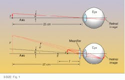
A magnifying glass magnifies because it allows the object under study to be brought nearer to the eye before going out of focus. For an adult with normal eyesight and no magnifier, objects can be brought no closer than about 25 cm from the eye, a distance called the near point (see Fig. 1, top). Any closer than that and the image on the retina blurs because the lens inside the eye can no longer compensate.But a magnifying lens placed directly in front of the eye overcomes the eye`s natural focal limit by forming a virtual image of the object that the eye can focus on. The optical illusion makes an object positioned just within the front focus of the magnifier (F) appear as though it were larger and located at the near point of the eye (see Fig. 1, bottom).
The angular size ratio between the virtual image and the real object at the near point determines the magnifier`s angular magnification: M = q`/q. But by using the thin-lens formula (see Back to Basics, April 1994, p. 89) and a little trigonometry, this simple ratio can also be expressed as a relation between the near-point distance (25 cm) and the focal length (f) of the magnifying lens: M = 25/f + 1. Thus, for a normal near-point distance of 25 cm, a 2.5-cm focal-length lens would have a magnifying power of 11, and the shorter the focal length, the higher the magnification.
Of course, as the focal length of the magnifier shrinks, so too does the size of the lens. This puts a practical limit on the power of simple magnifiers. Most, in fact, rarely exceed a magnification of 25, which corresponds to a focal length of approximately 1 cm.
Despite this fundamental limitation, the Dutchman Antoni van Leeuwenhoek (1632-1723) made startling discoveries in the latter half of the 17th century through simple microscopes that he constructed from specially polished glass beads as small as 1.5 mm in diameter. The field of view through one of Leeuwenhoek’s 1.5-mm glass micro spheres was extremely narrow, but the 1-mm focal length yielded a magnification of 251, according to the formula above. Amazingly, Leeuwenhoek became the first person to see human spermatozoa (1677) and bacteria (1683) using these crude but effective microscopes.
Compound microscopes
To achieve higher magnifications, a combination of lenses must be used, which defines a compound microscope. Although there is some question over who in vented the first compound microscope, many believe that a spectacle maker named Zacharias Janssen constructed the first one sometime around 1590 in Middelburg, Holland.
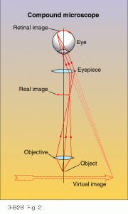
The basic compound microscope consists of two lenses aligned along their optical axes (see Fig. 2). The first lens, called the objective, forms a real image of the object, while the second lens, called the eyepiece, magnifies this image for the eye. The total magnification of both lenses (MT) equals the lateral magnification of the objective (mO = -x’/fO) times the angular magnification of the eyepiece (ME = 25/fE + 1). Thus MT = -25x’/fOfE + 1. In these formulas, x’ represents the distance of the real image from the objective`s back focus, and fO and fE symbolize the focal lengths of the objective and eyepiece, respectively.Essentially, the only difference between a simple magnifier and the eyepiece of a compound microscope is that the "object" of the eyepiece is not a real object but rather a real image of the object created by the objective. When the object itself is positioned a short distance x in front of the objective`s front focus, an enlarged, inverted real image forms behind the back focus by a sizable distance x’ = f2O/x. The eyepiece then forms a magnified virtual image of the real image at the near point of the eye, just like any magnifier.
Despite the higher magnifications attainable with compound microscopes, more than two centuries passed before their full potential could be realized. In fact, as late as 1829 an article in the London Encyclopedia characterized compound microscopes as "still best adapted for recreation." Lens aberrations were to blame for this--particularly chromatic aberration, which robs highly magnified images of their clarity.
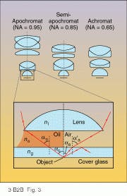
Chester Hall (1703-1771) discovered a remedy for chromatic aberration in 1733 when he combined two glass elements with different refractive indices into a single lens, but it took nearly a century to successfully adapt Hall`s achromatic design to the tiny lenses used for microscope objectives. Nevertheless, before the 19th century was out, three multielement optical designs had evolved for controlling the aberrations of objectives: achromats, semi-apochromats, and apochromats (see Fig. 3).Achromats are chromatically corrected for blue and red wavelengths and show no spherical aberration in the yellow, while apochromats exhibit better spherical-aberration control throughout the visible and are chromatically corrected at three wavelengths in the blue, yellow, and red. The performance of semi-apochromats is a compromise between the other two designs.
Because of their high performance, apochromatic objectives can achieve focal lengths as short as 1.5 mm and magnifications as high as 100. If paired with a 25X eyepiece, a 100X objective would produce a total magnification of 2500X. But at these elevated magnifications, aberrations become hard to control with the objective alone; therefore, multielement eyepieces are usually used to help correct residual aberrations such as lateral color and field curvature. For this reason, microscope manufacturers often provide matched pairs of objectives and eyepieces.
High magnifications introduce other complications, too. For example, as the focal length and corresponding diameter of the objective decrease, so too does the usable cone angle of light from the object. And a narrow cone of light entering the objective means poor image brightness and resolving power for the microscope. This is especially true when biological specimens must be viewed through a cover glass, in which case refraction and internal reflection can severely restrict the angle and intensity of light reaching the objective.
The standard measure for the maximum acceptance angle of an optical element is called its numerical aperture: NA = n sina, where n is the refractive index of the medium outside the optic (usually air) and a is the half angle of the widest acceptable light cone. It turns out that image brightness is proportional to (NA)2 and that resolving power d l/2NA, where l represents the wavelength of light. For the best resolution and image brightness, then, one should choose an objective with the highest NA.
In air, where n = 1, the highest possible NA for an objective is 1. Thus, the highest possible resolution is l/2. But if the first optical surface of the objective is immersed in water or oil with a refractive index higher than that of air, NA can exceed 1, thereby boosting resolution and image brightness. The practical limit of NA for an oil-immersion objective is about 1.5, which corresponds to a resolution of l/3.
At very high magnifications, the depth of focus of a microscope is not much more than its resolution, which could be 0.3 µm or less. This poses a problem for thick, transparent specimens under study, because defocused light from other portions of the specimen can wash out the fine detail in the focused image. To control this, specimens are usually sliced by a microtome into very thin sheets with thicknesses no greater than 10 times the resolution.
Illumination
The restriction on specimen thickness underscores the critical importance of illumination in microscopes. Most objects examined under microscopes are relatively transparent and so must be transilluminated to be seen. This makes the specimen and the light source integral parts of the optical system. In fact, as Max Born and Emil Wolf have shown, even the resolving power of a microscope depends partly on the coherence of its light source (see Further Reading).
In the most basic form of illumination, called brightfield illumination, an intense cone of light irradiates the specimen from behind, leading to a diffracted or refracted image of the object on a bright background. The two most common methods of brightfield illumination are critical illumination and Köhler illumination.
With critical illumination, a small, extended light source such as a tungsten filament or discharge arc is directly imaged by a condenser lens onto the object plane of the microscope. But Köhler illumination provides a more even light field because it uses a field lens to form a real image of the light source at the primary focus of the condenser lens. In both lighting systems, a system of apertures and corrector lenses is often employed to govern the brightness, size, and color fidelity of the light field.
Another type of illumination, known as darkfield illumination, generates a highlighted image of the specimen on a dark background. One popular version of this technique uses a special condenser (cardioid condenser) that creates a hollow cone of light with an angle greater than the acceptance angle of the objective. In this way, only light diffracted or scattered from a specimen at the apex of the light cone can enter the objective.
Objects also can be lighted directly from the side, which is the darkfield illumination method used by ultramicroscopes. Side-lighting enables the ultramicroscope to spot objects smaller than the optical resolution, although their shapes cannot be resolved.
Opaque objects, of course, must be viewed by light reflected off them. For low-power objectives with longer focal lengths, the light can be brought in at a downward angle from the side; higher-power objectives call for vertical illumination: the light must pass either through or around the objective to reach the specimen. Vertical illumination requires a beamsplitter or prism to direct light down the optical axis of the objective. For better image contrast, though, an annular beamsplitter is used to form a hollow tube of light that passes through a donut-shaped condenser encircling the objective. This lighting scheme, called epi-illumination, bypasses the objective altogether.
Specimens can be illuminated with UV and IR radiation, too, but this demands special optics. Objective lenses made of quartz or fluorite work well for high-resolution microscopy in the UV, while all-reflective optics can be used for both UV and IR work. At these invisible wavelengths, images are usually captured photographically or electronically. UV microscopes are particularly useful for fluorescence microscopy, in which specimens stained or "tagged" with distinctive fluorescent dyes are bathed in UV radiation and viewed through filters that isolate the resulting fluorescence.
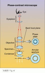
But one of the most original concepts of object illumination can be found in the phase-contrast microscope, for which Frits Zernike (1888-1966) won the Nobel prize in 1953. Zernike’s method renders a perfectly transparent object visible by converting the simple phase variations of the transmitted light wave into intensity variations that can be detected.
To convert a conventional brightfield microscope with coherent Köhler illumination into a phase-contrast microscope, an annular aperture is placed at the primary focus of the condenser (see Fig. 4). The condenser converts the hollow tube of light passing through this aperture into a hollow cone of light focused on the specimen. Unlike darkfield illumination, the light cone is narrow enough to pass through the objective, which then forms an image of the annular aperture at the back focal plane. Almost all of the light converging on this annular image has passed undiffracted through the specimen. But light diffracted by the specimen is spread across the entire back focal plane of the objective.Because of this physical separation between diffracted and undiffracted wavefronts, a matching annular phase plate properly positioned in the back focal plane can selectively modify their phases. It turns out that a 90° (quarter-wave) phase shift between the two wavefronts simulates the diffraction effect of a partially absorbing medium. Consequently, when viewed through the eyepiece of a phase-contrast microscope, a perfectly transparent object appears with the contrast typical of partially absorbing objects.
Zernike`s phase-contrast microscope revolutionized microscopy, but other microscopes also have been developed based on two or more wavefronts. For example, interference microscopes exploit the techniques of multiple-beam interferometry to create images with quantifiable phase differences, and polarization microscopes use polarized light to achieve the same effect with birefringent specimens.
Scanning microscopes
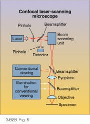
Since 1957, though, optical microscopes have advanced in a radically new direction. In that year, M. L. Minsky filed for a patent on a new kind of scanning microscope called a confocal scanning optical microscope (CSOM). Unlike a conventional microscope, in which the objective forms a complete magnified image of the object field, Minsky`s confocal microscope would build up images one point at a time by scanning the object back and forth over an illuminated pinhole, sort of like a TV raster. The advantages of this novel approach can be demonstrated by looking at a modern-day confocal laser scanning microscope.
The specimen is vertically illuminated by laser light passing through a pinhole, which is imaged as a diffraction-limited spot at the object plane of the objective (see Fig. 5). Light reflected from the specimen passes back through the optical train and is diverted through a second pinhole to the detector. But only when the second pinhole is exactly positioned at the conjugate image of the first pinhole can light reflected from the spot on the specimen reach the detector. A full image of the specimen is constructed one point at a time by raster scanning the spot across the object plane.Since peripheral light cannot pass through the detector pinhole, CSOM images of thick specimens suffer no loss of definition or contrast. Also, the raster nature of CSOM images makes them conducive to electronic processing and storage. By exploiting both of these advantages, CSOMs can construct three-dimensional images of objects by simply stacking successive layers of scanned two-dimensional images. Generating images from raster scans does take time, however. Nevertheless, some CSOMs can perform "real-time" microscopy by continuously scanning the object through thousands of pinholes in a spinning disk.
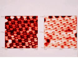
Yet despite these and other advantages, the lateral resolution of CSOMs—which can be quite good—is still fixed by the diffraction-limited width of the laser spot, which ultimately depends on the wavelength of the light. But recently, an ingenious new microscope called the near-field scanning optical microscope (NSOM) has broken through the once impenetrable barrier of wavelength-dependent resolution (see photo at top of this page). The original idea for NSOMs was proposed in 1928 by an Irishman named Edward H. Synge (1890-1957), but it took half a century to develop the technology needed to make it work, namely, lasers, subwavelength apertures, single-photon detectors, precision positioners, and computers.
The basic idea behind NSOMs is to literally reduce the optics, illumination area, and working distance to a fraction of a wavelength, which is defined as the near field. In the near field, resolution is mostly determined by the size of the aperture, not the wavelength of light.
In one commercial NSOM design (the Aurora TMX 2000 from TopoMetrix, Santa Clara, CA), the specimen is illuminated with 488-nm, argon-ion laser light passing through a tapered fiberoptic probe with a 50-nm aperture at the tip. Using a shear-force positioning feedback system, the specimen is scanned past the probe while maintaining a tip-to-specimen distance of 2-15 nm. But with only 10 nW of light dribbling out of the probe aperture, a photomultiplier must be used for photon detection and imaging. The specified resolution of the instrument is 50 nm or better—roughly l/10.
NSOMs are the new wave in optical microscopy, and they exploit an extensive variety of electro-optic technologies in their quest for higher resolution and better versatility. Although their development has only just begun, these instruments are carrying on a tradition of electro-optics that began 400 years ago with the simple magnifier.
ACKNOWLEDGMENT
The following people provided important background information for this article: Jay Trautman and Donna Cunningham, AT&T Bell Laboratories; and Tony Abbis and Patrick Moyer, TopoMetrix.
FURTHER READING
Richard J. Cherry, ed., New Techniques of Optical Microscopy and Microspectroscopy, CRC Press Inc., Boca Raton, FL (1991).
T. Wilson, ed., Confocal Microscopy, Academic Press, London, UK (1990).
E. H. Synge, Phil. Mag. 9, 1014 (1928).
E. Betzig and J. K. Trautman, Science 257, 189 (1992).
Max Born and Emil Wolf, Principles of Optics, 6th ed., Pergamon Press Ltd., Oxford, UK (1980).
About the Author
Thomas V. Higgins
Contributing Editor
Thomas V. Higgins was a contributing editor for Laser Focus World, covering science and technology.
