Laser gyros, lidars guide air and space craft
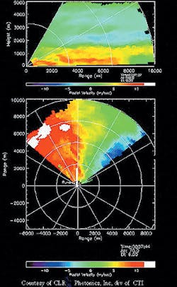
In the years to come, lidars that help pilots avoid turbulence will join laser gyros as standard navigational equipment on commercial airliners.
Since their commercialization nearly 20 years ago, laser gyros have become by far the most widely applied laser device in the aerospace field. Not only are they universal on airliners and rockets, but they are increasingly used on spacecraft as well. By the middle of the decade, however, a second laser technology may become just as vital to aircraft navigation—lidar that can detect clear air turbulence.
Guiding the way
Laser gyros are the standard method of inertial navigation for nearly all aircraft flying today. While Global Position Satellite (GPS) signals can give pilots an accurate location of their aircraft, inertial navigation is still essential to determine the aircraft heading and attitude, as well as dynamic measures such as rate of turn. For this task, laser gyros have long since replaced their mechanical gyroscope predecessors—they are more accurate, less expensive, and need less maintenance.
The basic principle of a laser gyroscope is the same as the one that is used by the more-primitive motion sensor in the human inner ear. In both cases the underlying idea is to sense the difference in rotational motion between the sensor and a reference body at rest in the inertial frame—a body without rotational motion. In the case of the inner ear, this body is the fluid in canals of the inner ear, which remains relatively motionless when the body rotates and produces signals from tiny hairs (or cilia) inside the inner ear. Of course, in this case frictional forces can rapidly cause the fluid to share the rotational motion of the body, producing the gross measurement inaccuracies we experience as dizziness or motion sickness.
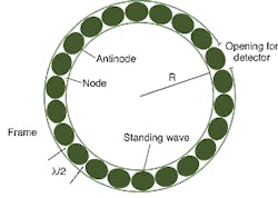
But with laser gyros, the immobile body is truly and absolutely immobile—it is the interference pattern set up by two counter-rotating beams of light. In a ring laser gyro, laser light is excited in a ring-shaped cavity, normally consisting of gas in a triangular cavity with mirrors at each vertex. Light of the same frequency travels in both directions around the ring, setting up a pattern of standing interference (see Fig. 1). When the ring gyro, which is fixed to the aircraft, rotates, this interference pattern remains motionless in a rotational sense, so the pattern drifts relative to the cavity. By sensing this drift, an absolute measurement of the rotation rate is obtained. There are no frictional forces at all, since the speed of light is independent of the motion of the objects that the light is reflected from or emitted by.The operation of the laser gyro is based on a simple but profound property of space. While special relativity describes how all linear motion in the universe is relative, with no preferred state of rest, there is a special inertial frame in which there is no rotation and no acceleration. Rotation and acceleration are absolute motions, not relative to some other body. This is a property of space that puzzled even Einstein. So counter-rotating laser beams will always set up a pattern that is fixed in this inertial frame, independent of the initial or current motion of the ring laser cavity.
To determine rotation in all three axes, sets of three mutually perpendicular laser gyros are used. Sets of six are often used for redundancy. In ring laser gyros, the lasing medium is almost always helium neon. Sensors may either detect the shift in the interference patterns—the phase of the pattern at a point—or they may detect its motion by the frequency shift of pattern as it moves by the sensor.
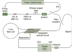
An alternative type of laser gyroscope is the fiberoptic gyroscope or FOG. Here laser beams are sent in opposite directions through a coil of optical fiber, generally about 1 km long (see Fig. 2). Again a sensor detects the phase difference when the two beams are made to interfere. The FOGs can be made considerably less expensively than ring-laser gyros, but until recently were not as sensitive, since they were affected by back scattering of the light.In theory, an extremely small rotation rate will induce a measurable shift in the phase of the interference pattern in practice, at small rotation rates, the two beams "lock up" with the interference pattern remaining locked to the mirrors. This behavior is due to a small amount of light being back-scattered from the mirror surface, instead of being reflected forward to the next leg of the ring. Thus, some of the light goes part way around the ring in one direction, and part in the other, canceling out the phase shift. This small signal in turn entrains the larger laser signal through nonlinear resonance effects. With sufficient rotation, these effects are too weak to matter and the phase shift emerges.
To avoid the lockup effect, most ring-laser gyros incorporate dithering—an electromechanical vibration of about 1 kHz that ensures the cavity is nearly always rotating faster than the lockup limit. By measuring the phase shift averaged over several cycles of dithering, the device can detect rotational speeds far below the lock-up limit. Some recent laboratory designs instead eliminate lockup by using mirrors that are extremely efficient reflectors, thereby eliminating the back scatter.
Laser altimeters
Laser gyros are not the only airborne navigational laser instrument now in use. For low-flying aircraft, including helicopters, accurate altimetry is critical and can be provided by laser devices. For altitudes up to 400 m, for example, Laser Optronix (Vallentuna, Sweden) offers a laser altimeter that is based on the common principle of all laser rangefinders—measuring the time delay from a pulse of light. The device provides 10 cm accuracy (a delay of 0.6 ns in round-trip time) with a 1000 Hz repetition rate using a 905-nm infrared diode laser. Built-in software distinguishes between ground reflection and return from vegetation by counting only the last or farthest-returned pulse.
Moving LIDAR into the market
Another laser-based aid to aviation is just on the verge of commercialization—lidar to detect clear-air turbulence. A research project funded for decades by the FAA, NASA, and the NOAA, lidar-based turbulence detectors will soon be moving into selected airports and, in not too many years, onto airliners. One of the most active participants in the field is an alliance of Coherent Technologies Inc. (Lafayette, CO) and Honeywell, which has already contracted to provide lidar detectors to an as-yet-undisclosed U.S. airport. A more ambitious project to develop lidar for commercial airliners, originally scheduled to reach the market in 2003, has been put on a temporary hold due to the sharp downturn in air travel, a decision that was made prior to last year's Sept. 11 terrorist attacks.
Lidar relies on an extraordinarily frequency-stable laser source to detect small Doppler shifts in a backscattered signal-frequency shifts on the order of a few megahertz or one part in a hundred million. In addition, when two lasers are used to measure wind velocities in two perpendicular directions they have to be wavelength-matched to the same accuracy. In measuring clear air turbulence, the backscatter relies on a relatively weak signal from aerosols in the atmosphere. As in radar, lidar determines range information from the time delay in the return from pulsed signals, and scan the beam rapidly in height and azimuth.
The problem of detecting turbulence is more complex than simply measuring wind velocity. Much of the effort in developing lidar for CAT (clear air turbulence) detection has gone into the development of software that can rapidly sort through an extremely large mass of data and report results in real time. The key phenomena that must be found is regions of wind shear, in which the direction of the wind changes rapidly in space.
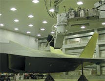
In CTI's commercially available lidar, called WindTracer, wind speed data is presented as a false-color map of a cross section of the atmosphere—for example, near or on an airport runway (see photo at top of page). The unit is small, mobile, and rugged and has been applied in several turbulence detection situations, including one case in which it mapped the winds from a forest fire close to the company's Lafayette, CO, headquarters.
Airborne lidar for CAT detection from commercial airlines is a more challenging application, as even faster scanning and data analysis is required. The potential market, however, is far larger—tens of thousands of commercial airliners as compared with hundreds of airports. While the current contraction of the air transportation industry will delay the introduction of airborne lidar, the rapid maturation of the technology makes it likely that such instruments will become widespread as soon as demand for new airliners recovers.—Eric J. Lerner
Lasers track aircraft-painting robot
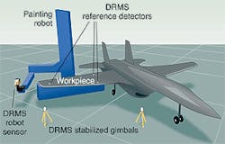
Painting a fighter airplane is a difficult task, as characteristics such as coat thickness are intentionally nonuniform across the aircraft. Engineers at Lockheed Martin (Marietta, GA) are putting into use a 30-ft-tall robotic painting system developed at Sandia National Laboratories (Albuquerque, NM) to spray-paint fighter aircraft; the robot can apply paint more precisely than the most skilled human (see figure below). The robot is mobile, however, so that its position in space is not intrinsically well-known. Although the engineers rigged up an optical interferometer to "tag" seven points in space for calibrating the robot, the interferometric system takes half a day to set up, can give different results depending on which crew is operating it, and provides only limited calibration points, according to Mike Cowan, staff applications engineer at Lockheed Martin."The DMRS establishes a coordinate system tied to the workpiece," explains Randy Goucher, ATA's director of business development. "With the real-time position measurement capability of DMRS, the speed at which the tool is being moved by the robot can also be determined—important to how the paint is applied."
To make sure that the air in the hangar housing the robot is not so turbulent as to prevent laser triangulation, engineers from ATA measured and approved the air characteristics at Lockheed Martin's facility. Goucher notes that although the DMRS will be used to calibrate the robotic painting system, it will not monitor the robot as it paints the aircraft, because thick clouds of paint aerosol would prevent clear laser transmission.
The DMRS has other potential uses, says Goucher. For example, it could aid in shipbuilding, where hull sections hundreds of feet on a side would have to be accurately positioned. The measurement accuracy of such a large-scale DMRS would be about 3 mm, he notes.—John Wallace
About the Author
Eric J. Lerner
Contributing Editor, Laser Focus World
Eric J. Lerner is a contributing editor for Laser Focus World.
John Wallace
Senior Technical Editor (1998-2022)
John Wallace was with Laser Focus World for nearly 25 years, retiring in late June 2022. He obtained a bachelor's degree in mechanical engineering and physics at Rutgers University and a master's in optical engineering at the University of Rochester. Before becoming an editor, John worked as an engineer at RCA, Exxon, Eastman Kodak, and GCA Corporation.
