Distance-measuring interferometers (DMIs) track an object's axial location as it moves by monitoring the phase change of a beam bouncing off a mirror mounted to the object. Although conventional DMIs can measure displacements down to small fractions of a wavelength, they cannot measure absolute distances. Such an interferometer has other disadvantages: for many applications it must be reset against a fixed reference point every time it is turned on, and if it botches a fringe count while operating, it must also be reset. Now, a DMI developed by researchers at Massachusetts Institute of Technology (MIT; Cambridge, MA) measures distances to subnanometer precision, and does it absolutely.1
Based on a Michelson interferometer, the device has a dual-wavelength light source—a 775-nm-emitting modelocked Ti:sapphire laser, and a continuous-wave 1550-nm-emitting laser diode—with the two beams collinear. The 775-nm beam has a coherence length much smaller than the distance to be measured and can be tuned over a 2-nm range, while the laser diode has a coherence length larger than the measurement distance. The reference mirror of the interferometer is scanned axially at a speed of 0.5 mm/s, inducing a Doppler shift in the reference beam. At the receiver, the two beams are separated with a dichroic mirror and the two signals measured by photodetectors. The corresponding phases of the beams are then extracted from their heterodyne signals.
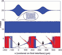
Using a phase-crossing technique, the MIT interferometer enables measurements to be simply done that were previously difficult. For example, the device can measure the optical distance between the front and back surfaces of a glass plate to better than a nanometer (see figure). In one case, the optical thickness of a piece of quartz coverslip was measured to be 351.0373 ±0.0004 μm. If the material thickness of the plate is determined by other means, the refractive index of the glass can then be found to a high degree of accuracy.
In another use, the ratio of refractive indices at two wavelengths—the relative dispersion—can be determined without knowing the plate's material thickness. The researchers replaced the laser diode with a tunable low-coherence superluminescent diode at 1550 nm, allowing the optical distance to be measured at that wavelength. Comparison with a previously measured distance at a 775-nm wavelength produced dispersion. Other light sources can give dispersion measurements at other wavelengths.
REFERENCE
1. C. Yang et al., Opt. Lett. (Jan. 15, 2002).
About the Author
John Wallace
Senior Technical Editor (1998-2022)
John Wallace was with Laser Focus World for nearly 25 years, retiring in late June 2022. He obtained a bachelor's degree in mechanical engineering and physics at Rutgers University and a master's in optical engineering at the University of Rochester. Before becoming an editor, John worked as an engineer at RCA, Exxon, Eastman Kodak, and GCA Corporation.
