Polarization control aids fiber component testing
Polarization control aids fiber component testing
Looped-fiber, optical-free-space, and liquid-crystal polarization controllers offer performance trade-offs in fiberoptic-network and test-system design.
Donald K. Wilson
The state of polarization (SOP) of an optical signal can affect insertion loss of fiberoptic components such as circulators, isolators, couplers, wavelength-division multiplexers, integrated optical devices, and fiber amplifiers. Accordingly, a polarization controller is often included ahead of such components for tests during design, manufacture, and incoming inspection. Measurements of polarization-dependent loss (PDL), polarization-dependent gain, and polarization mode dispersion require polarization control, as do performance diagnostics such as coupling ratio, return loss, output power, Jones matrix/Stokes parameter measurements, and swept-wavelength measurements.
For complex, multicomponent systems such as long-haul communications networks in which signal polarization may be randomly degraded by the fiber, minimum PDL should be specified for components. On the other hand, increased PDL can be traded off with other factors to improve the overall insertion loss of certain components and the total system.
The three common types of polarization controllers are mechanical looped-fiber devices, optical-free-space devices, and electronic liquid-crystal devices. Depending on the approach, polarization devices can be manually operated, motorized, or computer-controlled. Regardless of type, they commonly include three stages: a quarter-wave stage that transforms the incoming SOP into a linear SOP, a half-wave stage that rotates the linear SOP to a desired azimuth, and a final quarter-wave stage that transforms the linear SOP to any desired elliptical SOP. Any point on the polarization-defining Poincarè sphere can be addressed by adjusting these three stages. Each type of controller implements the operation differently, providing system designers with performance and cost trade-offs.
Polarization controllers incorporating four stages or combining two stages with a linear polarizer also exist. However, the classic three-stage version is more intuitive and amenable to analysis, especially in the context of this article.
All controllers accept any input SOP and provide any user-required output SOP. A three-stage unit does so with minimum insertion loss regardless of input SOP. The two-stage linear-polarizer combination works best with a defined input SOP but incurs higher losses for signals with elliptical SOPs.
Looped-fiber controller
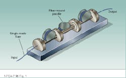
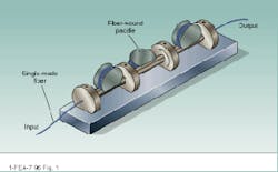
As its name suggests, the looped-fiber controller (LFC) consists of single-mode fiber wound around a series of movable "paddles" mounted on a rigid frame (see Fig. 1). When single-mode fiber is coiled into a loop, the controlled stress applied induces linear birefringence; the degree of birefringence is a function of fiber material, loop diameter, and fiber-cladding diameter.
For a given wavelength, the proper loop diameter will induce a phase retardation corresponding to a 90° phase change, just as with a quarter-wave plate in classical optics. Two loops wound on the same paddle are equivalent to a half-wave plate, inducing a 180° phase change. Tilting the paddles changes the orientations of the fast/slow axes, analogous to rotating a conventional optical wave plate.
Easy to build and comparatively inexpensive (typical cost is approximately $1000), the LFC is an obvious choice for laboratory applications. Indeed, many such controllers now in use are homemade rather than purchased. The LFC has virtually no internal insertion loss, and input/output losses can be minimized by well-executed fiber splices. In addition, the fiber can be changed to achieve different performance characteristics.
This type of controller does have drawbacks, however; foremost among them is polarization drift induced by thermal and mechanical sensitivity of the design. Expansion of the paddles changes the stress on tightly wound fibers and, hence, the phase retardation induced in the signal polarization. The fiber itself is also temperature sensitive; moreover, if loosely wound, the fiber can experience vibration-induced errors. Paddle vibration affects polarization, and random stresses on the fiber during paddle rotation can compromise performance.
All of these factors conspire against the precise quarter-half/quarter-wave arrangement and the availability of all possible output polarization states. The necessary frequent readjustment of paddles and fibers may be unacceptable, but sophisticated control mechanisms can mitigate many of these problems. For example, LFCs are the basis of auto-scanning computerized systems such as the Hewlett-Packard (Santa Rosa, CA) 11896A instrument. Interestingly, the more sophisticated HP 8169A polarization controller and a similar unit from JDS-Fitel (Ontario, Canada) use an optical-free-space approach based on two stages and a linear polarizer.
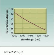
No amount of tweaking can overcome the inherent nonachromatic properties of the fiber used in LFCs, however. As wavelength changes, so will the phase shift of a given loop (see Fig. 2). If an LFC is to be used at multiple wavelengths, either the fiber or the controller must be changed at each stage of the test procedure. Simultaneous operation at different wavelengths, as in wavelength-division multiplexing and swept-frequency tests, is not possible.
Optical-free-space controller
The optical-free-space controller is the classical method of polarization control and uses individual birefringent phase-retardation plates for each of the quarter-half/quarter-wave sections. While the theoretical elegance of an all-fiber system may have diminished interest in traditional methods, a well-designed free-space controller has much to offer, especially for automated systems.
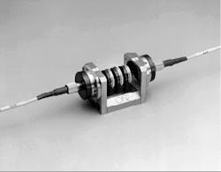
In the optical-free-space controller, easily interchangeable retarder modules are located in an open-air collimated-beam region created by input and output expanded-beam connectors (see Fig. 3). The devices offer far greater thermal stability than the LFC fiber-and-paddle arrangement, while remaining robust in the face of vibration and shock. With drift thus minimized, polarization states can be more accurately and repeatably addressed. An auxiliary, output linear polarizer can be included to achieve polarization ratios of up to 10,000:1.
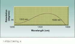
The basic design is readily adaptable to motorized control. Free-space units are more compact than LFCs, making them attractive for OEM applications. The Optics for Research FiberBench system in Fig. 3 can be readily miniaturized, whereas LFC dimensions are fixed by paddle size. Free-space controllers also offer the option of achromatic performance at specific wavelengths (see Fig. 4), making them suitable for wavelength-division multiplexing and swept-frequency measurements.
On the other hand, free-space controllers do suffer significantly higher insertion losses than LFCs (on the order of 0.5 dB) as a result of various internal optical losses and the use of expanded-beam connectors rather than splices. On the other hand, that same absence of fiber splices eliminates problems that may arise from splicing the single-mode LFC fiber to the multimode fibers of the component under test. Typical free-space polarization controllers cost about $2000; achromatic versions cost about $3000.
Liquid-crystal controller
Birefringence induced by a liquid-crystal device varies as a function of applied voltage. Liquid-crystal modules are thus well suited to polarization control. The liquid-crystal controller uses several retarder modules in a free-space arrangement, substituting liquid-crystal units for the conventional birefringent plates. Polarization control is entirely electrical, with phase retardation achieved over a voltage range from 0 to 5 V. The solid-state devices offer millisecond switching speeds, electronic temperature compensation, and computer controllability.
The liquid-crystal controller can be tuned to control phase retardation at any single wavelength, but the design is not achromatic. Thus, although it is more convenient to operate than the LFC, it cannot be used for real-time WDM measurements. Internal insertion loss is somewhat higher than with optical wave plates because of the conductive coatings applied to the faces of the retarders. As in free-space designs, connector losses may be incurred to produce a collimated beam region for the retarders.
A three-stage, liquid-crystal polarization controller with associated electronics costs about $3500--less if a two-stage/linear-polarizer combination is chosen. More-sophisticated computer-controlled versions also are available.
Extending the limits of fiberoptic system performance is increasingly dependent on the quality of the associated components, rather than the fiber. Use of polarization control in design, test, and manufacture of such components is certain to expand. Whichever control method is appropriate for a given application, the need can be satisfied at reasonable cost. o
FIGURE 1. In three-stage, looped-fiber polarization controllers, each turn of single-mode fiber around a paddle is equivalent to a conventional optical quarter-wave plate. Two loops are equivalent to a half-wave plate, and tilting the paddles is analogous to rotating the wave plate.
FIGURE 2. Inherent phase retardation of a looped-fiber controller varies with wavelength. Precise quarter-wave retardation for the fiber in this controller is achieved only at 1550 nm.
FIGURE 3. Three-stage, optical polarization controller, OFR model PC-FFB-S/P-1550-X, uses optical retarders mounted in a rigid frame. Expanded-beam input/output connectors establish the free-space region in which the retarders function.
FIGURE 4. Optical-free-space polarization controller can be designed for achromatic performance across the wavelengths of interest. The unit de scribed here achieves quarter-wave retardation both at 1310 and 1550 nm.
Designing looped-fiber polarization controllers
The design of a looped-fiber polarization controller is straightforward. The difference in refractive index Dn along the fast and slow axes of the material is given by
Dn = a(r/R)2
where a = 0.133, a constant related to the material of the fiber, r is the fiber-loo¥radius, and R is the paddle radius. The fiber is wound into a groove on the paddle, so r differs from R by the depth of this groove and the radius of the fiber itself.
The phase shift f induced by the loo¥can be expressed as
f = (2/l)Dn2R radians.
Assuming a desired phase shift of f = /2, we can restate this as
R = 8ar2/l.
At the standard telecommunications wavelengths of 830, 1300, and 1550 nm, standard single-mode fiber-loo¥radii to induce 90° phase shifts are 15.73, 10.04, and 8.42 mm, respectively.
D. W.
DONALD K. WILSON is president of Optics for Research, Box 82, Caldwell, NJ 07006.
