Phase-step calibration extends 19th century standard into 21st
Gauge blocks are still used as length standards in industry and trade primarily because they are easier and less expensive to handle than laser-based instruments
The authoritative reference standard for length used in industry for the last century or more has been the end standard or gauge block. This gauge is a bar, usually hardened steel, with two ends that are flat and parallel to a tolerance of 100 nm. Interferometry can measure the length of the bar to a high degree of accuracy when the bar is placed (in a procedure known as wringing) against a reference surface such as a very flat steel plate.
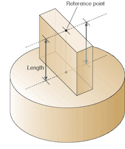
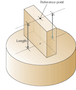
Gauge blocks come in a wide range of grades that define geometrical and surface-finish properties.1, 2 Some grades are commonly seen in machine-shop applications. Others, with optical-quality finishes, range in nominal length between 0.1 mm and 1 m. "Central length" is precisely defined as the optical height of the reference point relative to a datum plane, which is parallel to the measuring face of the gauge (see Fig. 1). The datum plane is referenced from the optically flat reference (or "platen") that is wrung to the gauge block.
The gauge-block length is determined by a method dating back to 1890 of analyzing the fringe shift across the optical step (see "More than a century of interferometry," below). There was little change in gauge-block interferometry for the first 70 years or so, but increasingly stringent industry requirements have recently transformed once-negligible measurement distortion from the wringing process into a significant source of uncertainty and a potential barrier to the use of end standards (see "Wringing the wrinkles out of wringing," below). So modern phase-step methods have been developed to allow quantitative analysis of small distortions where the block and reference surface meet, thereby avoiding small systematic errors in the length measurement.
Gauge-block length is evaluated by the method of exact fractions.3, 4 This technique takes the phase difference Dm (fractional-order displacement or fringe fraction) between the gauge measuring face and the platen reference surface from three or more known wavelengths, each in turn.
Optical gauge-block height can be expressed as
L = (m1 + Δm1)λ1/2 =
(m2 + Δm2)λ2/2 = (m3 + Δm3)λ3/2.
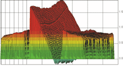
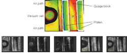
Gauge-block length estimated by an independent measurement aids in determining which group of integer interference orders (m1, m2, m3) correspond to the true length of the gauge block. Evaluation of fractional interference orders via phase-step interferometry offers nanometer-scale resolution of gauge-block central length, but only with thoughtful application. High-resolution contour maps of the gauge measuring face and platen reference offer an invaluable asset, enabling detailed analysis of surface form variations and optical diffraction observed at the sharp edges between the gauge and reference plane (see Fig. 2). The gauge block represented in Fig. 2 would actually be rejected as a length standard because of its unusually large nonparallelism, but the plot illustrates the improved capabilities for absolute gauge-block length measurement offered by advances in phase-step interferometry.
A low-noise configuration
Interferometer designs for gauge-block calibration load the gauge block and platen into the test arm such that the platen effectively replaces the test-arm mirror. Fizeau-style interferometers were at one time very popular for gauge-block applications, however the potential for asymmetrical interference-fringe profile makes fringe analysis more complicated than using a two-beam Twyman-Green design in which the fringe profile is an exact sinusoid.
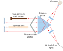
Figure 3: The Kösters interferometer setup at the Physikalisch-Technische Bundesanstalt (PTB; Braunschweig, Germany) hinges on the Kösters interfering prism and contains both a refractometer cell and the gauge block and platen (drawing not to scale). Test- and reference-beam paths are as close together as possible without overlapping in a compact, common-path design. The setup is more resistant to vibrational noise than interferometers with orthogonal beam paths and phase stepping is accomplished by rotating wedged plates in the beam.
The Kösters configuration is preferable for low-noise precision applications, and is particularly advantageous for gauge-block metrology since the test arm is in close physical proximity to the reference arm, meaning that the influence of spatial temperature variations on the refractive index of air are minimized (see Fig. 3).5 Some traditional gauge-block interferometer setups have been upgraded to phase stepping through hardware alterations to allow movement of the reference mirror, or addition of a rotating plate as the phase-stepping element. In the image field of the interferometer in Fig. 3, the measurands are the phase difference between gauge block and platen, and the phase difference between air and vacuum wavelength paths (see Fig. 4).
The largest influence contributing to the difference between an optical length measured with wavelengths in vacuum and mechanical length of a gauge block is the refractive index of air. The relationship between vacuum wavelength λ0, refractive index of air n, and wavelength in air λair is λ0 = nλair. Typically, empirical equations are used for the evaluation of refractivity (n – 1) based on measured values of air temperature, barometric pressure, and relative humidity.6–8 As in the image field of this phase-step interferometer example, the addition of a refractometer cell in the same image field as the gauge block adds little extra effort to the data analysis. But a real-time measurement of the optical-path-length difference between vacuum and the air in the interferometer allows measurement uncertainty associated with the refractivity correction to be reduced by almost an order of magnitude.
Phase change of light on reflection from a surface is also a significant contributor to measurement uncertainty in absolute length measurements. According to the definition of gauge-block length, the platen and gauge block should have the same material (typically steel) and surface-finish properties. A difference in reflection properties between the gauge and the platen can be a bothersome consideration for practical phase-step interferometry applications such as phase unwrapping; however, the most important implication is the evaluation of the length-equivalent correction to determine the mechanical gauge height. This phase-change correction is one of the largest contributions to measurement uncertainty of gauge-block calibration by optical interferometry. Considerable effort is devoted to understanding and evaluating its physical value.
references
- ISO 3650:1998(E) International Standard, "Length standards – Gauge Blocks," International Organization for Standardization, Geneva, Switzerland.
- T. Doiron and J. S. Beers, The Gage Block Handbook, NIST Monograph 180, U.S. Dept. of Commerce, National Inst. of Standards and Tech. (NIST), Gaithersburg, MD (1995).http://patapsco.nist.gov/mel/div821/
- M. Born, E. Wolf, Principles of Optics, 6th Ed., 290 (Pergamon Press, New York, 1980).
- P. Hariharan, Basics of Interferometry, 74 (Academic Press, Inc., Boston 1992).
- E. Decker, R. Schödel, G. Bönsch, Proc. of SPIE 5190, 14.
- K. P. Birch and M. J. Downs, Metrologia 31, 315 (1994).
- G. Bönsch, E. Potulski, Metrologia 35, 133 (1998).
- P. E. Ciddor, Appl. Opt. 35(9), 1566 (1996).
Jennifer Decker is a research officer at the Institute for National Measurement Standards (INMS), National Research Council Canada (NRC; Ottawa, Canada); e-mail: [email protected]. Ted Doiron is a physicist at the National Institute for Standards and Technology (NIST), Precision Engineering Division (Gaithersburg, MD); e-mail: [email protected]. RenÉ SchÖdel and Gerhard BÖnsch are both physicists at the Physikalisch-Technische Bundesanstalt (PTB), Bundesallee 100, D-38116, Braunschweig, Germany; e-mail: [email protected].
More than a century of interferometry
Standards of length in the form of metal bars had already been around for a long time in the early 1890s when a fresh perspective was brought to bear on length calibration in the labs of the Bureau international des poids et mesures (BIPM) in Paris. Michelson and Benoit demonstrated that the high-precision scale produced by wavelengths of light from an isotope lamp could be useful for practical calibration of gauge-block length, also advantageous because the scale is naturally occurring and indestructible.1 Although their interferometer was successful, it wouldn't be until 1960 that the Système international d'unités (SI) defined the meter in terms of a number of wavelengths of one of the krypton 86 emission spectra, and in 1983 as the length of the path traveled by light in vacuum during 1/299792458 second. This latter definition relies on a defined value for the speed of light, in practice permitting realization of the definition of the meter with any one of numerous allowed frequency-stabilized optical sources listed in the CIPM Mise en Pratique.2
At base, length interferometry demands suitable coherent optical light sources. Isotope lamps were traditionally used as wavelength standards but today the superior coherence of frequency-stabilized lasers is preferred. Wavelengths are commonly based on the Mise recommendations but may in principle be directly obtained by optical-frequency measurements.3 At the moment, frequency-comb techniques can provide absolute accuracies on the order of 10–14, related in a phase-locked chain to the cesium clock frequency standard and limited by the realization uncertainty of the cesium clock.
Transferring the accuracy of a well-known laser frequency to a material artifact presents obstacles, however, which phase-step interferometry is helping to overcome. Today's best measurement capability for gauge-block length calibration provides an expanded uncertainty (U) on the order of 70 nm (based on a coverage factor k = 2 or approximately 95% confidence) for a good-quality 1-m gauge block, or U less than 20 nm for a 25-mm nominal length. There is a big difference between the accuracy of the best wavelength standard and the best optical gauge-block calibration but considering all possibilities for propagation of the definition of the meter, gauge blocks are still used in industry and trade primarily because they are easier and less expensive to handle than laser-based instruments.
REFERENCEs
- A. A. Michelson and J. R. Benoit, Trav. et Mem. Int. Bur. Poids et Mes. 11, 1 (1895).
- T. J. Quinn, Metrologia 40(2), 103 (2003).
- J. Ye, H. Schnatz, and L. W. Hollberg , IEEE J. Sel. Topics in Quant. Electr. 9, ( 4) 1041 (2003).
Wringing the wrinkles out of wringing
The wringing technique allows two similarly polished flat surfaces (platen and gauge block in this case) to adhere to each other upon contact as a result of molecular forces. It is similar to optical contacting except that gauge block and platen can be separated when the measurement has been completed. Relative to the capability of reading interference fringes, however, wringing is not a very repeatable process, and can lead to sophisticated platen flexing behaviors depending on the material and geometrical characteristics of gauge and platen. Platen flexing is problematic for the application of high-resolution phase-stepping instruments because phase measurement must consider the error contribution from this form variation relative to the ideal plane.
Making observations by eye, an experienced observer is able to intuitively perform smoothing and averaging to compensate for the flexing errors. This intuition is difficult to program into a data-analysis routine, so methods of averaging and extrapolation of the slope of the reference plane due to flexing can enable important corrections to the fringe-fraction measurement. Without correct modeling of these form influences, the method of exact fractions can break down, yielding erroneous results.
