Airborne lidar system profiles wind fields
J. A. Overbeck, M. S. Salisbury, and R. Richmond
Winds affect airborne operations, particularly cargo parachute deliveries and conventional bomb drops, in which objects released from an aircraft fall to the ground without guidance controls. If the wind field at the delivery/target area is known, the cargo-release point can be adjusted to compensate for the intervening winds.
Aircraft crews currently obtain wind data from local weather stations or from balloon launches (radiosondes). While accurate, this information is not always available for payload delivery in remote or hostile locations. The alternate approach of taking wind measurements at various altitudes using air speed during flight lacks the accuracy and completeness of radiosonde or weather-bureau data and can compromise aircraft safety. All of these methods have limited utility; the optimum approach would involve an aircraft-integrated sensor able to accurately measure real-time wind fields at any location. Lidar, or laser radar for aerosol sensing, provides one solution to this problem.
The Interim Operation Capability (IOC) unit is an airborne lidar system for wind-field velocity evaluation. Built for demonstration purposes, the unit can be rapidly installed on operational Air Force aircraft to provide near-term measurement capabilities for air-drop missions. In keeping with the goals of low cost and rapid integration, the IOC unit was assembled from commercially available subsystems not designed or engineered for airborne applications.
Transceiver design
In conventional heterodyne laser-radar systems, a transmitter sends an output beam toward a target. The Doppler-shifted return signal is mixed with output from a frequency-shifted local oscillator, forming a beat frequency from which the Doppler frequency and, hence, the target velocity can be derived. In the case of wind-field measurements, the targets are particles suspended in the air. The IOC system consists of a transceiver, scanner, signal processor, and support equipment mounted in the cargo bay of a C-141 aircraft (see Fig. 1). The transceiver source is a flashlamp-pumped, chromium- and thulium codoped yttrium aluminum garnet (Cr, Tm:YAG) laser operating at 2 µm. Built by Coherent Technologies Inc. (CTI, Lafayette, CO), the Q-switched system provides 50-mJ pulses at a 7-Hz repetition rate.
The transceiver was initially designed for a laboratory environment; to "harden" the unit for airborne operation, CTI converted the existing free-space heterodyne mixing scheme to an all-fiberoptic heterodyne mixing scheme, substituted a higher-power robust laser head for the master oscillator, and replaced the standard optical mounts with locking flexure mounts. Because aircraft velocities combined with wind-field velocities can yield Doppler shifts on the order of 䕠 MHz, the transceiver was modified to increase the frequency shift of the local oscillator from 57 to 97 MHz.
Transceiver mounting
Driven mainly by the lack of a dedicated aircraft for our use, a fundamental design requirement was that the system should be compatible with any C-141 cargo aircraft and permit rapid installation. Including operator/personnel stations and ancillary electronics and hardware, the entire system takes up the first two pallet stations behind the cockpit bulkhead (see Fig. 2). It does not significantly reduce the aircraft`s operational use, as 11 pallet stations remain. By taking advantage of existing holes and panels in the aircraft and using a pallet system to carry the instrumentation, we made it possible to install the system, fly a mission, and remove the system in less than a day.Mounted on vibration isolators, the transceiver rests in an environmental enclosure equipped with a heat exchanger and filled with dry air. A 10X refractive telescope in the transceiver expands the diameter of the transmitted beam to 4 cm before the beam passes through a 4-in. fused-silica window in the bottom of the enclosure. The entire unit is hard-mounted to the cargo bay floor over a 3-in. hole in the floor near the cockpit. Although a larger transceiver aperture would have been desirable, the diameter is constrained by the size of the available exit port.
The scanner assembly consists of a folding mirror and a mirror mounted to a 14° wedge attached to a stepper motor. The scanner mirror produces a 20° × 28° (half angle) elliptically conical scan pattern with the minor axis located along the aircraft`s longitudinal axis. Software-controlled, the scanner stares at a user-defined number of positions around the scan while the system collects a selectable number of shots at each point for signal averaging. The assembly mounts underneath the cargo bay in an empty compartment originally designed for Doppler-radar antennae.
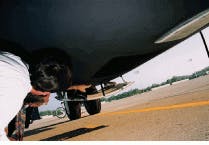
The beam exits the skin of the aircraft through a 12-in., optically flat, fused-silica window mounted in a small panel manufactured to replace an existing aircraft access panel (see Fig. 3). Because the panel is just behind the front landing gear, a shutter was added to protect the window from damage during takeoff and landing.The system is controlled by a Sun SparcServer 630MP using an Analytek 2000RM high-speed digitizer with a 250-MHz bandwidth for data collection. The workstation controls the scanner and digitizer, in addition to processing the returns on a shot-by-shot basis. The workstation also averages the returns to produce line-of-sight (LOS) velocity profiles and then uses these profiles in a vertical-azimuth-display algorithm to produce the full three-dimensional wind profile. With the addition of aircraft air-speed and ground-track information derived from an inertial-navigation system or global-positioning system, the data can be transformed into earth-fixed coordinates. A monitor displays the continuously updated version of the calculated wind field.
In its present configuration, the software begins data acquisition immediately after the laser pulse is transmitted. The maximum digitizer rate of 250 MHz/s and the 8 Kbytes of memory of the digitizer (1 Kbyte is reserved for digitization of the monitor pulse) limits data collection to a LOS range of 4.3 km. For the scan angles of this system, this translates to a vertical distance of 3.8 km.
Flight experiments and system performance
To assess ruggedness added to the system by our modifications, the transceiver underwent a broad frequency-vibration test at 2.1 g, far more severe than the typical 0.16-g environment the system encounters during flight on a C-141 aircraft. The transceiver took atmospheric data during the vibration test and showed no performance degradation under these conditions.
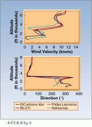
In late June 1995, the first flight tests were conducted at Wright-Patterson Air Force Base (OH), primarily to evaluate the full operational capabilities of the system hardware/software and to compare the results with ground-based wind-measurement systems. The ground-based systems included radiosonde, the Wright Laboratory 2-µm ground-based lidar (operated by CTI), and the Phillips Laboratory (Hanscom AFB, MA) ground-based 10-µm system. The systems were run in conjunction with the lidar-equipped C-141 flying overhead, and test results showed a good correlation among all systems (see Fig. 4).Although the IOC system was designed to measure winds for air-drop missions typically occurring at or below 15,000 ft, we were asked to assist in a high-altitude bombing test above 30,000 ft. The mission objective was to demonstrate that an airborne lidar system could improve the high-altitude bombing accuracy of B-52 bombers by measuring large shifts in wind conditions (mainly the jet stream) between aircraft and target.
At the Utah Test and Training Range (Hill AFB, UT), the lidar-equipped C-141 measured wind fields over the target area. The information was radioed to the B-52 bombardiers, who adjusted the payload-release points accordingly. This test was performed in conjunction with Phillips Laboratory and with support from the 93rd Bomb Squadron, the 49th Test Squadron, and the 445th Airlift Wing.
Low concentrations of high-altitude aerosols during the flight test, verified by the Phillips Laboratory ground-based CO2 system, hampered the measurement of full-wind profiles beneath our 34,500-ft altitude flight pattern. To compensate, we supplemented our wind profiles with the winds at altitude as measured by the B-52 aircraft during its ascent. The resulting wind profile consisted of an accurate lidar-measured profile up to the system`s typical operational altitude of 15,000 ft, with an approximation of the winds beyond this point. Using this profile, the bombers could correct for the wind and substantially improve their drop accuracy.
The IOC system is the first airborne, eye-safe, solid-state, vertical wind-profiling laser-radar system. Considering the number of civilian applications, transitions to the commercial industry give airborne lidar systems a bright future.
ACKNOWLEDGMENTS
The authors would like to acknowledge the efforts and assistance of the following individuals who collaborated on this project: R. H. Fetner, S. Buchsbaum, E. E. Armstrong, D. T. Brodbeck, L. T. Masters, and P. D. Woodworth.
J. A. OVERBECK and M. S. SALISBURY are with Technology/Scientific Services Inc., POB 3065, Overlook Branch, Dayton, OH 45437; [email protected]. R. RICHMOND is with USAF Wright Laboratory Active Systems Section, WL/AARI-2 Bldg. 622, 3109 P St., W-PAFB, OH 45433-7700.


