BIOLOGICAL IMAGING: Optofluidics reinvents the microscope
CHANGHUEI YANG, XIN HENG, AND DEMETRI PSALTIS
The invention of microscopy between the 16th and 17th centuries enabled the direct viewing of cells and other microsize objects for the first time. Since then, microscopes have become ubiquitous and vital laboratory tools, particularly for applications in medical and biological imaging. While different microscope variants have been developed that provide additional functions, the basic microscope design has undergone very few fundamental changes over the years.
New technologies and optical devices developed over the past couple of decades, however, can lead to fundamental changes in microscope design (see www.laserfocusworld.com/articles/259933). Using these new technologies, we have demonstrated an optofluidic microscope (OFM)-based on a fusion of optical and microfluidic technologies-that could easily be made small and inexpensive enough to change the way bioscientists tackle imaging problems.
Three primary functions
Historically, one of the primary functions of a microscope has been to replicate an image of an object onto a person’s retina. With the development of microelectronics processing technology, CMOS- and CCD-detector grids have been substituted for the retina. Nevertheless, the vast majority of microscopes still operate by relaying and replicating an object’s image onto a sensor grid of some sort. Another primary function of a microscope is to magnify the image so that objects of microscopic size are adequately resolved. Human 20/20 vision roughly corresponds to a pixel size of about 5 µm on the retina (this approximation is simply meant to give a sense of scale), so magnification is invariably required to resolve submicron features. The third primary microscope function is optical sectioning or selecting a specific plane in the object for imaging.
We can do away with the need for an image replication function if we are willing to rethink the way we use a CCD- or CMOS-sensor grid. Unlike with the human retina, we can place the specimen of interest directly onto such a sensor grid. By illuminating the specimen uniformly, its image can be directly recorded by the sensor grid. The lack of optical elements in this arrangement implies that there is no aberration or collection numerical aperture to worry about. Such an imaging strategy mirrors the phenomenon of floaters in the eye and has recently been implemented as an imaging method (see “Floaters in your eyes,” above).1, 2 In this case, the resolution is equal to the pixel size of the sensor grid-the smaller the pixel size, the better the resolution. Such an imaging scheme cannot be expected to perform better than a conventional microscope (which has resolution ranging from 0.2 to 1 µm), as the pixel size of commercial CCD or CMOS sensors ranges upward from 5 µm. The OFM method we recently developed at Caltech is very similar to this imaging strategy, but it has one vital difference: the resolution is not contrained by the sensor-pixel size. Using an OFM prototype, we were able to image fluid-immersible objects with a level of microscopic resolution on the order of 0.5 µm.3, 4
OFM prototype
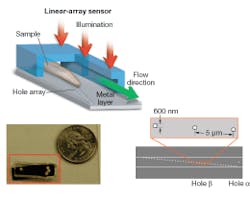
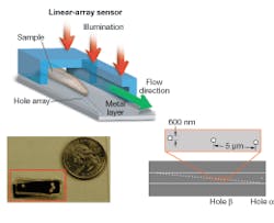
Our OFM device was fabricated as follows. First, a layer of metal was coated onto a linear sensor array to block out light. A line of holes was then punched into the metal layer. Finally, a microfluidic channel was added on top of the entire chip.
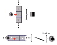
In operation, the device is uniformly illuminated from the top and the target object is flowed across the hole array (see Fig. 1). The time-varying light transmission through the hole constitutes a transmission-image line trace across the object. By stacking the line traces from all holes together, we can construct a transmission image of the object. The exact arrangement of the hole array with respect to the underlying pixel grid is the key novel aspect of the OFM (see Fig. 2).
We used our prototype to acquire OFM images of a Caenorhabditis elegans, a soil nematode commonly used to study the genetics of development and neurobiology. We compared the OFM images with an image acquired using a conventional microscope of similar resolving power (see Fig. 3). The comparable image quality verifies that the OFM method is capable of delivering high-resolution images. The prototype contained 600-nm-wide holes spaced at 5 µm intervals. In this prototype, the metal layer was also not directly bonded onto a linear-array sensor. Instead, transmissions through the holes were projected onto a linear CCD array by relay optics.
Notably, even though this prototype microscopy method does not perform image replication and magnification-two functions that are associated with conventional microscopy, it is demonstrably capable of delivering high resolution. More important, it achieves high resolution without the use of bulk optical elements. Optofluidic-microscope devices can be built onto chips with existing fabrication techniques and can be potentially mass manufactured at low cost (around $10). While the method does not provide optical sectioning, we are working on a variant that is potentially capable of such. This variant will be capable of high-resolution phase and amplitude measurements of the optical wavefront with a similar on-chip system; knowing the wavefront, we should then be able to perform virtual focusing into the sample of interest.
The dual advantages of compactness and low cost in this prototype design open up a wide range of possible applications. The OFM can be used in white-blood-counting cytometry devices, for instance, as image-based cell-type discriminators. Clinicians can use such units as disposable point-of-care units, and battlefield medics can easily carry these devices as they perform their jobs. Third World health workers can use the OFMs as cheap and compact microscope systems that they can easily carry in their pockets from village to village for malaria diagnosis.
Potentially tens or even hundreds of OFMs can be fabricated onto a single chip. Such a device could be used to parallelize the imaging of a large number of microorganisms and dramatically improve throughput. Taking a long view, the OFM may even form the imaging component of an implantable device that can be implanted into a person to provide continual monitoring of objects in the blood stream. Such a device may be useful for screening circulating tumor cells and other abnormal objects to provide early warnings of developing diseases.
ACKNOWLEDGMENT
This work is supported by the DARPA Center for Optofluidic Integration.
REFERENCES
1. D. Lange, C.W. Storment, C.A. Conley, G.T.A. Kovacs, Sensors And Actuators B-Chemical107, 904 (2005).
2. M.L. Adams, M. Enzelberger, S. Quake, A. Scherer, Sensors and Actuators A-Physical 104, 25 (2003).
3. D. Psaltis, R.S. Quake, C. Yang, Nature 442, 381 (2006).
4. X. Heng et al., Lab On A Chip 6, 1274 (2006).
CHANGHUEI YANG is an assistant professor, XIN HENG is a graduate student, and DEMETRI PSALTIS is the Thomas G. Myers Professor in the Electrical Engineering Department and Bioengineering Department, 13 Moore, Caltech, 1200 E. California Blvd, MC136-93, Pasadena, CA 91125; e-mail: [email protected]; www.optofluidics.caltech.edu.
Floaters in your eyes
Have you ever looked up at a clear blue sky and seen spindly objects floating in your field of view? Those highly resolved images are caused by debris in the vitreous humor of your eye that has moved very close to your retina layer. Under uniform illumination (such as that of a clear sky), the debris project clear shadows onto your retinal layer. Remarkably, the lens in the eye plays no part in this imaging process. To verify this, the next time you see floaters, try focusing and defocusing your sight. The floaters should remain equally sharp.


