Passive optical networks (PONs) have attracted attention for their potential to drive down the cost of distributing signals via optical fibers. They divide the signal from a single central transmitter among many outgoing fibers, each going to a separate receiver for a separate customer. Separate transmitters at each customer site return signals to the central distribution point, so users share the system's total transmission capacity. The system is often called a B-PON, for broadband passive optical network.
A key advantage of this approach is that it uses only passive components—fibers, couplers, and connectors—in the outdoor distribution network. Transmitters and receivers are installed only indoors, at the end points, and other active components such as switches are avoided. This approach avoids the need for electrical power between the central distribution node and the subscriber, and reduces the costs of network hardware, installation, operation, and maintenance. These attractions have led to development of passive optical networks for distribution to business customers, local nodes, and fiber-to-the-home and fiber-to-the-curb-systems.
PON concepts
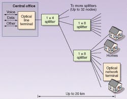
A passive optical network is essentially a two-way point-to-multipoint system (see Fig. 1). The downstream data signal originates with a single transmitter at a central point, such as a telephone central office. Passive optical couplers divide this signal among output fibers that distribute the same signal to all customers. The receiver at the customer end selects only the data directed to that terminal, discarding data directed to other users. Thus the data stream from the transmitter is divided among users.
Each customer terminal has its own transmitter, all of which can return upstream signals to the central distribution point. Upstream transmission may go through the same fibers as downstream transmission, or through separate fibers. Because all the signals go back to a single receiver, separate time slots are assigned to the transmitters at each subscriber terminal so they don't interfere with each other.
Current standard passive optical networks are based on the Full-Service Access Network (FSAN) standard (www.fsan.net). Originally developed for telephone applications, FSAN specifies downstream and upstream transmission at 155 or 622 Mbit/s; the two rates can be combined with 622 Mbit/s downstream and 155 Mbit/s upstream, and an intermediate 330-Mbit/s system is being tested. An FSAN standard for transmission in the gigabit range is in development, but the exact data rate has not been established.
The FSAN standard calls for transmission using asynchronous transfer mode (ATM), which breaks data into 53-byte cells consisting of a 5-byte header and a 48-byte data payload. Designed to handle voice, video, and data signals, ATM is widely used by incumbent local telephone companies. The cell structure can guarantee a fixed data rate to provide the quality of service needed for voice telephone lines or standard telephone rates such as T1 and T3.
Packet-switched data also can be repackaged into ATM cells, so an ATM PON can transmit Ethernet data. As with other signals, the Ethernet data is repackaged into ATM format at the transmitter, transmitted in ATM form, then converted back to Ethernet at the receiver. The ATM packaging accommodates the inherent burstiness of the Ethernet data stream, and the user "sees" an Ethernet PON, although the signals pass through the fiber as ATM cells. Current versions carry 10- or 100-Mbit/s Ethernet; the gigabit PON in development also will carry Gigabit Ethernet.
Alternatively, a passive optical network can carry signals internally in Ethernet format. Some proprietary passive optical networks transmit in Ethernet format, and work has started on Ethernet PON standards. The Institute of Electrical and Electronics Engineers has formed a study group on Ethernet in the First Mile, which is investigating Gigabit Ethernet transmission over copper, point-to-point fiber links, and passive optical networks. A Gigabit Ethernet PON would use optical hardware essentially identical to that for an ATM PON at the same speed; the difference would be in the software and electronics.
Optical terminals
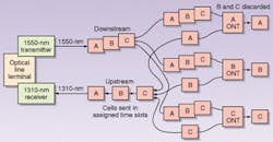
The central distribution terminal at the left side of Fig. 1 serves as the central controller for the passive optical network and provides an interface with the outside world. Many of these terminals can be assembled in one location, each serving its own group of subscriber terminals. The FSAN standard calls this controller and transmitter an optical line terminal (OLT). The terminals at the subscriber end are called optical network terminals (ONTs), and they provide interfaces between the network and the subscriber's equipment. Losses inherent in signal splitting limit one OLT to serving no more than 32 ONTs.Standard PONs work at two or three wavelengths (see Fig. 2). The OLT includes a distributed-feedback laser transmitting downstream at 1550 nm, which couples more than a milliwatt into the output fiber. Each cell or packet in the downstream signal carries the address of its destination terminal. Passive splitters divide the light among all terminals, but each terminal only reads those packets addressed to it. The downstream data transmission also provides timing signals needed to control upstream transmission, which is at 1310 nm. The FSAN standard also provides for a third wavelength channel at 1490 nm.
Subscribers pay for a certain data rate, which is a fraction of the total. The rates chosen depend on the application; for business subscribers, they often are based on increments of standard rates in the digital telephone hierarchy, such as several 1.5-Mbit/s T1 lines. Software allocates transmission capacity to each terminal, so it can be changed as necessary.
Upstream transmission
Optical line terminals can use relatively expensive 1550-nm transmitters because each PON requires only one of them. However, PONs require many more ONTs, so they must be relatively inexpensive, and operate in the less-controllable environment of the customer site. This led to the choice of lower-cost 1310-nm transmitters for the upstream channels.
Upstream transmission goes through a network of fibers that are combined with passive couplers, so all transmitters send their signals to one receiver in the OLT. To keep these signals from interfering with each other, PONs use a time-division multiple-access protocol that assigns different time slots to each ONT. Each subscriber terminal turns on and transmits signals upstream during its assigned time slot, then switches off so the next can begin transmitting. The control software allocates these time slots, and downstream transmission provides the clock signals to synchronize upstream transmission by all subscriber terminals. This divides upstream capacity among users in the same way downstream capacity is divided. Depending on the application, total upstream capacity may be less than the downstream capacity; for example, residential customers need more data-transmission capacity downstream than upstream.
Careful synchronization of upstream transmission is necessary to avoid collisions. Each ONT is at a different distance from the central OLT, so the system measures those distances and incorporates the proper delays into its programming of subscriber ONTs. The need to control these delays limits maximum transmission distance to 20 km. A burst-mode receiver in the ONT receives all the signals, keeping track of their sources.
Fiber architecture and WDM
All PONs use single-mode fibers, with signals divided by splitters. The placement and number of splitters depend on system design. Systems with a few high-capacity customers may require only a single 1 x 8 splitter; those with many low-capacity customers may have a 1 x 4 splitter followed by a 1 x 8. The splitters are purely passive devices that require no power, so they can be placed in splice cases or enclosures anywhere between the distribution center and the subscribers. For example, in a fiber to the home architecture, a single fiber could run to a curbside splitter that divides the signals among a couple dozen homes.
The FSAN standard provides for both single- and dual-fiber systems and each have their attractions. A single-fiber system reduces fiber costs by transmitting upstream and downstream signals through the same fibers. The trade-off is that it requires wavelength-division multiplexing (WDM) optics on both ends of the system. The choices depend on the application.
Optical Solutions Inc. (Minneapolis, MN) decided on a two-fiber architecture for its residential systems to avoid the added cost and complexity of WDM optics. One added consideration from their viewpoint was the ability to dedicate one fiber to downstream distribution of analog video signals for cable television. Two-fiber systems offer better isolation, and isolation is particularly important for analog transmission, said Bob Lund, chief technology officer. Thus Optical Solutions will use one fiber for downstream analog video transmission, with a second for two-way digital transmission of voice, data, and digital video.
Quantum Bridge Communications (Andover, MA) has developed a system that overlays extra wavelengths onto a fiber in its business-oriented PON to multiply total capacity, avoiding the need to lay new fiber. For example, if a new customer wanted Gigabit Ethernet service, the carrier could add a wavelength dedicated to that service. Quantum Bridge has developed an eight-channel "optical edge switch" for the purpose, using dense WDM; four of the overlay units can be stacked to provide a total of 32 wavelengths on the PON.
Applications
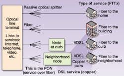
Developers of the FSAN standard envisioned a hierarchy of applications (see Fig. 3). One intent was to allow the fiber service to evolve, starting with fiber distribution to nodes, neighborhoods, or businesses, then evolving to fiber to the curb and fiber to the home as customer requirements increased. Bringing fiber to a neighborhood node could overcome the distance limitations of digital subscriber line (DSL), leaving comparatively short distance to be spanned by copper cables, and allowing faster DSL connections to residential subscribers. SBC Communications (San Antonio, TX) is taking this approach in its ambitious Project Pronto, which seeks to bring fiber to within at most 9000 ft. (2.7 km) of subscriber homes in its territory in the southwestern United States.Elsewhere, PONs are being deployed directly to homes and to businesses. Fiber-to-the-home PONs include video as well as voice and data. One approach adds a separate downstream analog video channel to the conventional downstream and upstream digital channels. A second adds switched digital video to the digital data stream, with a set-top box controlling the signals transmitted in the ATM signal through the fiber. That system behaves like a conventional cable network, although its internal operation is different. In both cases, the fiber delivers the optical signal to an interface box at the home, where the signals are converted to electronic form for distribution through the home.
A variety of companies are developing fiber-to-the-business PONs, including SBC, Comcast Business Communications (Philadelphia, PA), competitive local-exchange carriers, and electric utilities. Many want to capitalize on their existing fiber networks by linking them to business customers who need more bandwidth but don't want to pay for a dedicated fiber line.
The main competition for PONs in delivering services to business and residential subscribers comes from point-to-point Gigabit Ethernet links. Although the point-to-point design requires more optical transmitters and receivers, it can take advantage of the low cost of mass-produced Ethernet terminals. Developers of both approaches think they have the advantage; time will tell which approach works best for what applications.
ACKNOWLEDGMENT
Thanks to Todd Cabral of Quantum Bridge Communications, and Bob Lund of Optical Solutions.
About the Author
Jeff Hecht
Contributing Editor
Jeff Hecht is a regular contributing editor to Laser Focus World and has been covering the laser industry for 35 years. A prolific book author, Jeff's published works include “Understanding Fiber Optics,” “Understanding Lasers,” “The Laser Guidebook,” and “Beam Weapons: The Next Arms Race.” He also has written books on the histories of lasers and fiber optics, including “City of Light: The Story of Fiber Optics,” and “Beam: The Race to Make the Laser.” Find out more at jeffhecht.com.


