High-power Raman fiber lasers test components
Bill Holtkamp and Dirk Kuizenga
Optical power of several watts, high reliability, and emission at important wavelengths make the Raman fiber laser useful for component testing.The development and introduction of increasingly dense wavelength-division-multiplexing (WDM) schemes has in turn created a growing market for higher-power components. For example, in the case of optical amplifiers, the gain of a single amplifier must now be divided among a larger number of channels. To maintain the same transmission distance between amplifiers, the amplifier power must be increased accordingly.
As with all telecommunications devices, these amplifiers and their individual components need to be tested extensively during both development and volume production. Such testing requires a light source capable of delivering several watts of power into a single-mode fiber at key wavelengths. A newly developed Raman fiber laser uniquely meets this requirement.
The Raman fiber laser
When intense light propagates down the core of a single-mode fiber, the light scatters off vibrational modes of the molecular bonds in the glass, exciting these bonds and generating a small amount of light downshifted by the molecular-bond frequency (13.2 THz for the silicon-oxygen bond in silica glass). The downshifted light results from the spontaneous Raman effect.
When high-power pump light in a fiber core is combined with light from a weaker source that is frequency-downshifted by 13.2 THz, the pump light will produce gain at the downshifted signal wavelength. This effect is known as stimulated Raman scattering. In a specific example, a pump source at 1117 nm will produce gain at 1175 nm. If mirrors in the form of fiber Bragg gratings (FBGs) at 1175 nm are put at both ends of a single-mode fiber that is a few hundred meters long, the 1175-nm signal can oscillate between these mirrors, forming a Raman fiber laser (RFL).
The strong signal at 1175 nm that oscillates between the gratings can be used as the pump for another Raman laser at 1239 nm. This is done by putting another set of gratings at each end of the fiber to produce an RFL at 1239 nm. The resulting device is called a cascaded RFL. The cascading process can be repeated several times. For example, in a fiber laser with five cascades and a pump at 1117 nm, the output wavelength is 1480 nm, which is the pump-source wavelength for erbium-doped fiber amplifiers (EDFAs).
The Raman effect is quite weak for normal propagating laser beams, requiring high-peak-power Q-switched lasers to produce a Raman laser. However, in fiberswhere the beam is confined to an 8-µm diameter in a single-mode core over hundreds of metersthe Raman process now becomes very strong and efficient; a few watts of continuous-wave pump power at 1117 nm can produce 1480-nm light with better than 25% efficiency.
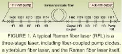
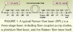
In a practical high-power Raman fiber laser, the output from a 35-W, fiber-coupled semiconductor-laser bar is used to pump the cladding of a double-clad ytterbium (Yb) fiber laser (see Fig. 1). The light from the Yb fiber laser then enters a cascaded Raman resonator, which has FBG end mirrors. This cascaded Raman resonator shifts the wavelength of the input light to the desired value.
Raman fiber lasers can produce output at virtually any wavelength within the transparency range of the Raman fiber. This is done by selecting gratings to set the output wavelength of the Yb fiber laser, and by tailoring the RFL gratings to select the number of cascades in the RFL. Such an RFL can be factory-configured for either 2.5- or 5-W output at 1480 nm (the EDFA pump and L-band Raman-amplifier pump wavelength) or 1455 nm (the C-band Raman-amplifier pump wavelength). Other standard wavelengths, including 1450, 1427, and 1365 nm, are also available.
All the optical components and power supply for the RFL are contained in a single unit. Output power is controlled via an RS-232 interface, simplifying integration into any test setup. With the system in constant power mode, the power supply precisely locks the output of the laser to eliminate power variations, thus ensuring stable, long-term test conditions.
Testing applications
The RFL is now used by several telecommunications-component manufacturers to test components with power ratings between 0.5 and 2 W. For example, New Focus (San Jose, CA) uses RFLs to test its line of passive components, including optical circulators, polarization-beam combiners/splitters, and various thin-film pump/pump combiners, pump/signal combiners and bandsplitters, said Brian Rapela, a test engineer at New Focus. The company tests devices singly, and also sets up series arrangements for simultaneous testing of multiple components.
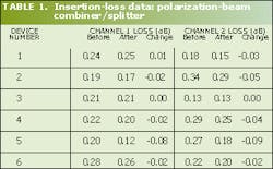
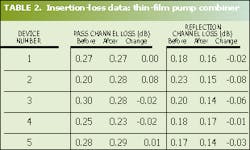
In the series setup, fiber-tap couplers that split off approximately 1% of the power are located before and after each component. Once calibrated, the difference in the signal between consecutive taps allows accurate real-time determination of the insertion lossand any changes in insertion lossfor each component under test. The devices are also routinely removed from the test to measure other optical parameters. High-power tests of a polarization-beam combiner/splitter and a thin-film pump combiner result in insertion-loss data (see Tables 1 and 2). These devices maintained all optical properties with little change after being exposed to 5 W of power for 500 hours, while at the same time undergoing cycling over their operating temperature range.
JDS Uniphase (Nepean, Ont., Canada) uses RFLs to test its passive components, which include couplers, polarization-based couplers, isolators, hybrids, and pump/signal WDM combiners. Most of the high-power versions of these components are destined for use in Raman amplifiers. "We essentially use [RFLs] as ageing sources; that is, to stress the parts under test," said Michael Robertson, manager of materials characterization. "We are involved with two distinct levels of testing. Specifically, we use these tests to prove designs for new parts and new fabrication methods, as well as for sampling tests from actual production lines."
Daisy-chain testing
Production-line sampling involves subjecting components to the full 5 W of laser power for periods of less than five minutes. Verification of process changes or new designs uses a daisy-chain setup (see Fig. 2). Some components are continuously tested in this type of rig for up to thousands of hours. The components are tested within an environmental chamber, allowing them to be subjected to high humidity and temperature cycling, as well as high power during the tests.
Test engineers look for any change in insertion loss, said Robertson. However, other performance specifications, like return loss, might degrade without initially manifesting a big change in insertion loss. "For this reason, full optical characterization of the parts is performed before testing and after the parts have been removed from the high-power test setup," explained Robertson.
Along with the high power of the RFLwhich permits testing of a string of devices simultaneously at a power level that far exceeds rated operational levels for the componentsthe laser's reliability allows it to provide full power at all times. These two considerations far outweigh other performance characteristics, according to Robertson. For example, although the RFL has very little noise, test engineers look for significant changes in insertion loss using ratioed signals, so fairly high noise levels could be tolerated.
JDS Uniphase now has RFLs for testing fused-fiber components. "We believe that this type of testing will eventually become part of the overall Telcordia suite of testing protocols," said Robertson.
Engineers at OZ Optics (Carp, Ont., Canada), a maker of high-power polarization components for optical amplifiers, use a 5-W RFL for component testing but sometimes attenuate its output, since most of the company's components are specified for operation up to 2 W or less. "We often take advantage of the laser's high power to split the output and run two test rigs in parallel," said Omar Sezerman, president of OZ Optics.
Because most of its products are based on polarization, engineers at OZ Optics have developed a polarization controller that can be readily coupled to the front of RFLs. Relying on stress-induced polarization, this device delivers a linear polarization state that can be freely rotated. The RFL is also used by the company to test a high-power, lens-style, noncontact connector. The company expects to see its customers also setting up for standard testing of their own bare components and integrated devices using RFLs.
BILL HOLTKAMP is director of sales and DIRK KUIZENGA is product manager at Spectra Physics Telecom, 1335 Terra Bella Ave., Mountain View, CA 94043; e-mail: [email protected].


