Laser mapping aids cleanup efforts at World Trade Center site
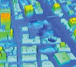
Laser-based thermal mapping is playing a key role in helping officials better assess the damage done by the Sept. 11 terrorist attacks on the World Trade Center (WTC). Researchers from the University of Florida are using airborne laser swath mapping (ALSM) and ground-based scanning laser technology to collect hundreds of millions of laser-range measurements of the surface of the ground, buildings, and rubble in and around Ground Zero (see figure).
Other project participants include the Joint precision Strike Demonstration group of the US Department of Defense, the National Oceanic and Atmospheric Administration, the National Geodetic Survey, and Optech (Toronto, Canada), which manufactures the laser instrumentation. The project is being supported in part by a $45,000 National Science Foundation grant. The NSF is interested in developing a "before and after" database that would allow them to assess internal damage to airports, bridges, buildings, and other structures in the wake of an earthquake, and sees the WTC project as a first step in this direction.
"The attack on the World Trade Center and Pentagon created not only a human tragedy but infrastructural devastation as well," said Dave Bloomquist, a University of Florida professor of civil and coastal engineering." Besides the hundreds of thousands of tons of debris, several surrounding buildings near Ground Zero may not be structurally salvable, and there is concern that several are slowly deteriorating."
Standard surveying techniques used to assess the condition of a damaged building or structure are time-consuming and only a few select points are scrutinized. Airborne laser swath mapping is similar to LIDAR and LADAR but is used most often to map "hard" targets like topography rather than "soft" targets, such as the atmosphere.
System configuration
In a typical ALSM setup, a pulsed laser ranging system is mounted in an aircraft equipped with a precise navigation system and an opening (or window) through which the laser pulses can be directed toward the ground. The aircraft is flown over an area to be mapped and the area is scanned with the laser. The round-trip travel times of the laser pulses from the aircraft to the ground are measured and recorded, along with the position and orientation of the aircraft at the time of transmission of each pulse. After the flight the vectors from the aircraft to the ground are combined with the aircraft position at the time of each range measurement and the three-dimensional (3-D) coordinates of each ground point are computed.
By accurately timing the round-trip travel time of the light pulses from the laser to a reflecting surface it is possible to determine the distance from the laser to the surface, typically with a precision of 1 cm or better. Using a rotating mirror inside the laser transmitter, the laser pulses can be made to sweep through an angle, tracing out a line on the reflecting surface. Reversing the direction of rotation at a selected angular interval makes the laser pulses scan back and forth along a line.
The position and orientation of the aircraft at the time that each pulse istransmitted is determined using phase-differenced kinematic global positioning system (GPS) techniques. A GPS receiver is mounted in the aircraft and one or more receivers are located at ground stations in the area to be mapped. The GPS observations are collected at 1-s intervals. As long as the airplane is within 30 or 40 km of a ground station, its position can be determined to within 3 to 5 cm. The laser pulses are time-tagged using GPS time. The orientation of the aircraft is determined using an inertial navigation system (gyroscopes and accelerometers). Once X, Y, and Z coordinates of the ground surface have been extracted for each reflection, an equally spaced grid of heights can be computed by interpolation and contour maps and cross sections can be produced.
The WTC mapping project involves the use of both an airborne and a ground-based laser—in both cases, an Optech ALTM 2033 with a Kodak 420 color digital camera attached to the laser-sensor unit. The 1047-nm airborne laser provides data points spaced at 1 to 2 ft, while the ground-based scanning laser provides supplementary high-resolution coverage, with points spaced at the 1- to 2-in. level. Performance specifications include 30,000 laser pulses per second and the recording of two stops per pulse, including the intensity of each. The digital camera CCD array is rectangular, with approximately 1600 x 1000 elements, for a total of 1.6 million elements. The system was mounted in a Cessna Citation provided by the National Oceanic and Atmospheric Administration.
The first ASLM data of a 10-sq-mile area around the WTC were collected Sept. 23. Additional observations continued through Sept. 27. The data are being analyzed and turned into 3-D images at the University of Florida. When the airborne and ground-based observations are combined, they will provide 3-D models of the disaster sites that are far more detailed and accurate than has ever before been available, Bloomquist said.
About the Author
Kathy Kincade
Contributing Editor
Kathy Kincade is the founding editor of BioOptics World and a veteran reporter on optical technologies for biomedicine. She also served as the editor-in-chief of DrBicuspid.com, a web portal for dental professionals.