Planar photonic crystals move toward wider use
Emerging technology is enabling consistent signal enhancement over photonic-crystal surfaces large enough to handle real-world applications.
Photonic crystals are formed by etching or constructing 2-D or 3-D arrays of shaped structures into a dielectric medium. Although by no means confined to the optical regime, when fabricated with submicron dimensions these arrays form the optical analogy of a semiconductor material, meaning that photons are either allowed or nonallowed states of the lattice depending on their energy. Two-dimensional structures with usable properties in the optical regime that offer considerable flexibility of design for photonic-crystal lattices are relatively easy to generate-either as photonic-crystal fibers using conventional fiber-drawing techniques (see “Microstructured fibers carve themselves specialized niches,” p. 119) or as planar photonic-crystal (PC) devices using standard wafer-fab methods.
Although regarded for some time as an interesting exercise, the manufacture of planar PC devices has benefited from several advances and now these devices exhibit significant promise for real applications, and in certain cases have already reached the production line. Interestingly enough, not all of the applications are in photonics-the enhancement of Raman signals, for instance, is primarily of interest to the fields of forensics, pharmaceuticals, and general biochemistry.
Geometric considerations
Applications for PCs fall into two generic categories based on either the reflective or transmissive attributes of a photonic crystal.
The first includes spectral filtering, micron-scale optical interconnects, and high-efficiency microcavity laser devices.1, 2 All of these applications predominantly make use of the reflective properties of a photonic bandgap to either confine light within a microcavity or line-defect waveguide, or to provide back-reflection over a certain stop band. In a microcavity laser device, for example, light is generated within the gain material, radiating in all directions simultaneously. For this category of application it is desirable to ensure that the properties of the bandgap are as isotropic as possible, thus helping to reduce the linewidth of the laser emission and to improve the spatial mode profile.
The second set of generic applications includes spatial beam steering, polarization control, and optical time delay. These require transmission of light directly across the lattice, in which light must couple from the external environment (usually via an input waveguide) into guided Bloch modes that propagate within the PC. Because properties of guided modes in photonic crystals are described by dispersion relations, the greater the curvature, the stronger these effects become (see “Properties depend on dispersion relations,” p. 95).
Given that requirements for the two sets of applications are different in terms of the required shape and curvature of the dispersion relations, for a given material system the geometrical requirements are also different-the lattice geometry and its associated spatial symmetry is directly responsible for the curvature of the dispersion relations and thus directly affect the optical properties.
Reduction of loss
Geometrical considerations alone are not sufficient to ensure the acceptance of photonic crystals as useful commercial devices, and one of the key factors to be addressed when contemplating this issue is loss reduction.
To reduce (insertion) loss, optical engineers normally take great pains to eliminate scattering centers by minimizing surface roughness in rib and ridge waveguides used in optical components such as Y-splitters and arrayed waveguide gratings (AWG). In the case of a photonic-crystal component, however, strong scattering centers (in the form of deeply etched holes) are deliberately introduced into the waveguide to modify its dispersion. The walls of these shaped structures can cumulatively possess considerable surface area, and are by no means smooth or even necessarily perfectly parallel. Light incident upon these dielectric boundaries during its journey across the photonic-crystal lattice can be partially scattered out of the waveguide, assisted in part by a lack of waveguide confinement out of the plane of the lattice.
This problem can be reduced by filling the holes with another dielectric material, such that wave-guiding conditions are partially restored within the spatial regions of the holes. It is then possible to reduce losses over a very wide spectral range by up to 20 dB. More important, losses at the edges of the bandgap can be significantly reduced, thus allowing efficient coupling from the external world to some of the slowest Bloch modes. This means that performance of devices such as optical-time-delay and superprism-based spectrometers can be improved.
Superprisms
Structures with lower, naturally occurring symmetries such as simple rectangular, are characterized by strongly varying dispersion relations, dependent on both wavelength and propagation direction. Suitable choice of lattice symmetry and materials allows specific dispersive attributes to be designed into a PC optical component, including chromatic separation over specific bands of light as well as some very unusual chromatic beam-steering properties.
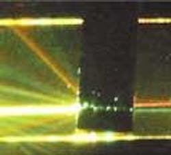
There is currently great interest in “superprisms”-optical components that make use of this phenomenon to separate different wavelengths within very small regions on a chip, thereby offering an order of magnitude smaller footprint than conventional devices such as AWGs (see Fig. 1). These devices could in the future find useful applications in integrated sensing, for example as a dispersive element that is part of an optical biosensor.
Quasi-crystals
Although the most common geometries are based on naturally occurring symmetries, such as square or triangular, PC structures can also be generated with unusually high levels of symmetry. Structures exhibiting these “artificial” symmetries are generically termed quasi-crystals, and can be found in other fields outside photonics.
The degree of lattice symmetry affects the properties of the associated dispersion relations, allowing the design of much flatter curvature and much weaker direction-dependent properties (isotropic). In addition, the contrast in refractive index required to create a bandgap can be significantly reduced, and thus also the losses.3
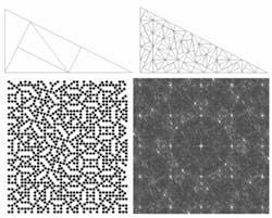
A pinwheel lattice structure is constructed by recursively subdividing a right-angle triangle (see Fig. 2, top). Circular (air) rods are created at the vertices to form the lattice (see Fig. 2, bottom left). Each subdivision introduces a new set of scattering planes at slightly different angles, and no set of angular planes is ever deliberately repeated. The Fourier transform (FT) of this structure, instead of exhibiting a well-defined “reciprocal lattice” as one would expect for simple symmetries, reveals the gradual formation of a “blurred” ring with a few distinct Bragg peaks (see Fig. 2, bottom right). As the number of iterations (and the overall size of the lattice) increases, the ring improves in definition, and the stronger peaks become less distinct. Taking a closer look at the fine structure of this ring, we find that it actually exhibits a fractal nature.
Finite-difference time-domain (FDTD) simulations reveal that this lattice does not actually possess “true” bandgaps, but instead provides very strong localization. This effectively results in a reduction in the density of optical states, similar at least to the formation of a bandgap, but instead of light being reflected from the structure, it becomes almost trapped within the lattice. Light trapped in this way either takes a very long time to traverse the lattice or eventually leaks out through imperfections in the structure. Such lattices may have applications for reducing cavity lengths in laser devices.
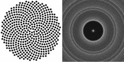
Another planar lattice-based on the Fibonacci series-is similar to the central part of a sunflower (see Fig. 3, left). This structure provides an extremely dense packing scheme with the natural inclusion of a microcavity at the very center. The FT of this lattice reveals a clearly defined circular ring, with a well-defined central Bragg spot confirming that the structure has near-circular symmetry (see Fig. 3, right). The FDTD simulations show that this structure possesses a true photonic bandgap, making it particularly suitable for laser applications in which improved light-extraction efficiency in conjunction with a near-circular spatial mode is also desirable.4
SERS biosensor
Drawing on some of the design criteria mentioned above, and subsequently coating planar structures with a thin layer of gold allows yet another set of modes to be created and manipulated-surface plasmons. Again, geometry and periodicity determine the spatial and dispersive properties, but this time for surface (as opposed to bulk) localized states.
Under certain conditions, light incident upon the surface couples into the surface modes and propagates some distance along the surface (see Fig. 4). If a molecular species is placed on this surface, the light can couple efficiently out of the surface plasmon mode and interact with vibrational modes of the molecule. This is simply Raman scattering, with the extraordinary addition that the effective cross section for the Raman interaction on these surfaces can be significantly enhanced by more than a millionfold. This is more commonly known as surface-enhanced Raman spectroscopy (SERS).
Discovered 30 years ago, SERS requires the proximity of a microscopically rough metal surface to induce a significant enhancement of the Raman backscatter from molecules. The physical mechanism is generally attributed to plasmon localization at “sharp” surface features, with previous surface methodologies having relied on roughened gold surfaces, silver (or gold) colloidal suspensions, and more recently metal nano-arrays. The binding of molecules to single gold nanoparticles has also yielded Raman signal enhancement.
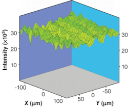
That none of these technologies has reached a sizable level of commercial success is because of the unacceptable inconsistency of the enhancement, even over a single 5 × 5-mm surface. Enhancement is often only observed at so-called “hot spots,” with little or no enhancement seen at neighboring locations. Not so for the emerging planar PC devices designed specifically for this application, in which the degree of consistency seen across a surface, and indeed between separate surfaces, is exceptionally high (see Fig. 5).
Careful modeling and subsequent design implementation indicate that parameters such as the level of enhancement and overall reproducibility can be tightly controlled. The indications are that features such as shape, depth, and pitch of the holes allow control over the degree of enhancement observed, while aspects such as spatial symmetry of the structure allow control over the level of consistency across a surface.
REFERENCES
1. J. D. Joannopoulos, P. R. Villleneuve, and S. Fan Nature 386, 143 (1997).
2. O. J. Painter et al., J. Lightwave Technology 17(11) 2082 (November 1999).
3. M. E. Zoorob, et al., Nature 404, 740 (2000).
4. U.S. Patent 6775448.
MARTIN CHARLTON is senior research manager and JOHN LINCOLN is director of business development at Mesophotonics, 2 Venture Rd., Chilworth Science Park, Southampton, SO16 7NP, England. GREGORY FLINN is a consultant to the photonics industry; e-mail: [email protected]; [email protected].
Properties depend on dispersion realtions
The allowed states (or modes) supported by the periodic lattice in a photonic-crystal material are usually known as “Bloch modes,” whereas ranges of nonallowed states are designated as “photonic bandgaps.” To broadly generalize, a given wavelength of light incident on the lattice is thus either transmitted through the lattice or reflected, respectively.
Permitted states in a photonic crystal can, just as for semiconductors, be represented by curved dispersion relations (also known as energy/k-vector diagrams). In this case the dispersion relations provide vital information about exactly how photons of a given energy (wavelength) travel within the lattice-for example, the curvature relates to the group velocity in the photonic crystal. The degree of this curvature is largely dictated by the geometry of the lattice, whereas the “bandgaps” are predominantly determined by the contrast in index of refraction between the materials used in constructing the physical lattice.
