The contrast between today’s computer-fueled research, engineering, and development and the more-empirical approach to engineering that predominated around the time of the inception of Laser Focus in 1965 can be striking. Experiment will, of course, always be fundamental to R&D. But now we have personal computers to simulate in great detail what may happen in a test run, and then capture and analyze what indeed did happen. Back then, most engineers relied on equations, numerical tables, slide rules, and experiments that minimized the need for numerical analysis.
While elegance in design and experimentation resulted in marvels such as the television, Trans World Airlines, and the Ford Fairlane 500, it sometimes fell short when the ultimate in knowledge regarding a physical process was required. As just one example, the laser lab of today has computer-based instruments that characterize laser-beam quality quickly, easily, and to a quantitative level difficult to achieve in 1965.
Getting carded
Given the same set of focusing optics, a higher-quality laser beam can be focused to a smaller spot than a beam of lesser quality, resulting in higher peak intensity. One way to measure beam quality is to determine the beam’s waist size and angular divergence, then multiply the two together; the resulting number is smaller for better-quality (lower-transverse-mode) beams, and is a minimum for fundamental-transverse-mode beams. Thus was born the card-carrying laser engineer, who might draw a series of different-size circles on an index card or sheet of paper and match the circles to laser-beam diameters near and far to crudely determine beam quality.
Many variants of this technique existed, including the use of upconversion materials for IR lasers, or examining burn marks on various materials for high-power lasers. (It should be noted that “beam quality” is a loaded term; some applications require multimode beams for best operation, so a “high-quality” beam is not always desirable.)
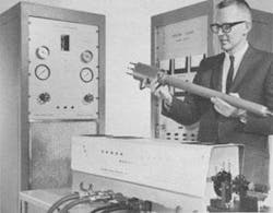
But, as described in the April 1, 1965, issue of Laser Focus, scientists at the Westinghouse Defense and Space Center (Baltimore, MD) developed a photographic beam-profiling technique that resulted in much greater detail. Developed for use with high-power ruby-laser beams (but first tested on a HeNe laser), the technique was based on an extended-range photographic film capable of photographing objects having a “variance in intensity over a ratio of 1:108.” The film contained three layers of emulsion with sensitivities ranging from 400 ASA (the fast layer) to 0.004 ASA (the slow layer).
The three layers were superimposed on a standard film base, and were all exposed simultaneously. Plastic-film beamsplitters called pellicles attenuated the laser beam to prevent overexposure (the beamsplitters were manufactured by National Photocolor of Mamoroneck, NY—a company that, 40 years later, is still producing pellicles). Although all three layers of emulsion were panchromatic, each layer was labeled with a different “dye coupler” that absorbed a single color (red, blue, or green) and was transparent to the other two, allowing the developed image in each layer to be viewed in light of the proper color. Microdensitometer scans allowed the researchers to laboriously construct 3-D beam-profile plots.The Westinghouse engineers grappled with the experimental vagaries of laser-beam propagation. “Measurements showed that the focal point is not as well-defined as previously thought,” they noted. “The energy plots revealed the manner in which the point of maximum energy varied as a function of position from the lens. Energy density was found by dividing peak energy by the spot diameter squared. The point of highest energy was not always the point having the smallest diameter.”
Even with their quantitative measurements, the Westinghouse engineers had no single standard way to define beam quality. That capability arose years later, with the advent of the M-squared (M2) parameter. In the May 1991 issue of Laser Focus World, Jim Darchuk, then director of marketing and sales at Photon (Santa Clara CA) and now at JDS Uniphase (San Jose, CA), noted that the International Standards Organization (ISO; Paris, France) was considering a proposal to standardize the measurement of laser-beam spatial parameters; the proposal included the specification of mode quality M, or the factor by which the product of actual angular divergence and waist size exceeded the ideal (M2, rather than M, is now universally used). A concise explanation of the M-squared method, as well as its advantages and disadvantages, was given in a talk presented by Anthony Siegman of Stanford University (Stanford, CA) at the Optical Society of America’s 1997 annual meeting, and published the following year.1
The M2 debate
The proposal, even when adopted and in common use, was not without controversy. In the July 1994 issue of Laser Focus World, George Lawrence, president of Applied Optics Research, presented a number of situations in which certain aberrations or diffracting objects within beams can create an M2 higher than would be apparent by the practical usability of the beam. In the September 1994 Laser Focus World, Lutz Langhans of Carl Baasel Lasertechnik (Starnberg, Germany) argued that “the examples Lawrence gives, where the M2 seems to fail, are not very relevant for practical purposes,” and cites the fact that some of the examples are near-field examples and thus not applicable in ordinary far-field use. In contrast, Gary Forrest of SensorPhysics (Carmel, CA) agreed with Lawrence, saying that this was why the SensorPhysics beam-measurement system provided other relevant properties such as divergence and astigmatism as well as M2.
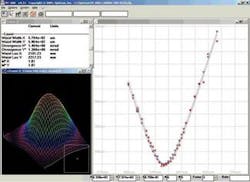
While the M2 approach is not perfect, it does work well as a standard, especially for good-quality beams. Understanding beam properties in detail is made easy with today’s approaches to modeling, measurement, and analysis (see figure). For those who are not too exacting, however, an index card is cheaper.❏
REFERENCE
1. A.E. Siegman, “How to (Maybe) Measure Laser Beam Quality,” in DPSS Lasers: Applications and Issues (OSA TOPS Vol. 17), M.W. Dowley, Ed., OSA, Washington D.C. (1998).
Inside Laser Focus
November 1965
■* Laser proposed as replacement for umbilical cables
* Study under way on laser commmunications problems* Atmospheric limits on laser propagation* Which type of laser should be used for trimming microcircuit elements?* Lasers aid in thin-film study* Lasers as microelectronic tool* More on measuring atmospheric particles via laser photography* ‘Two-in-one’ CW laser produces high powers at high efficiency* Hologram visual displays* Efficiency of neodymium-doped lasers upped 50%* Supersensitive light detector boosts prospects of laser communications* Traser reaches production stage* Swedes build laser rangefinder* CO2 lasers produce 130 watts, 13.8% efficiency* Tunnel effect produces visible laser light * Self-switching laser material-A special reportnull
About the Author
John Wallace
Senior Technical Editor (1998-2022)
John Wallace was with Laser Focus World for nearly 25 years, retiring in late June 2022. He obtained a bachelor's degree in mechanical engineering and physics at Rutgers University and a master's in optical engineering at the University of Rochester. Before becoming an editor, John worked as an engineer at RCA, Exxon, Eastman Kodak, and GCA Corporation.


