ULTRAFAST FIBEROPTICS: Narrow pulsewidths simplify dispersion mapping
By relying on picosecond pulsewidths for fiberoptic data transmission, researchers at AT&T Labs (Red Bank, NJ) and at Lucent Technologies (Holmdel, NJ) have achieved record distances between amplifiers at high data rates, while minimizing the need for complex dispersion mapping. The AT&T results were reported in November during a postdeadline session at the annual meeting of IEEE Lasers and Electro-Optics Society (San Francisco, CA). The Lucent results were reported in September during a postdeadline session at the European Conference on Optical Communication (ECOC; Nice, France).
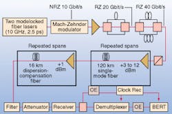
The AT&T researchers reported 40 Gbit/s transmission over six 120-km spans of conventional single-mode fiber (SMF), with dispersion compensation performed only at the end of the full 720-km span. Narrow-pulsewidth signals (2.5 ps at 1550 nm) for the experiment were generated using a commercially available modelocked erbium-doped fiber ring laser. Modulation at 10 Gbit/s was performed using a lithium niobate Mach-Zehnder modulator before optical interleaving of the signal into a 40-Gbit/s data stream (see figure).
Because the bit period at 40 Gbit was about 25 ps, the pulses took only approximately 10% of the bit period. One way to describe the return-to-zero (RZ) narrow-pulse format might be to call it the opposite of a soliton, according to Alan Gnauck, lead author on the AT&T Labs research paper. "Instead of keeping the pulse together, we do exactly the opposite," he said. "We want to blow it apart as quickly as possible. We've begun calling these pulses 'tedons', referring to the agricultural practice of dispersing or 'tedding' new-mown hay."
The narrow, high-frequency-content pulses tend to spread rapidly in the presence of fiber dispersion, which reduces the effects of self-phase modulation on the edges of the pulses in the bit stream. "We are making use of the fact that these narrow pulses will disperse so quickly that the pulse edges are not maintained long enough for the nonlinearity to have a large effect," Gnauck said.
The narrow pulses thus enabled the researchers to launch higher power into the fiber segments than they would have been able to using a conventional non-return-to-zero (NRZ) data format. The power launched into each SMF span varied from 3 to 12 dBm, and in each SMF span average loss was 27 dB with dispersion of 2040 ps/nm.
One drawback of the AT&T method is that the narrow-pulsewidth signals present a broad bandwidth that might limit the density of signal packing in wavelength-division-multiplexing applications. "So in one sense you're trading off spectral efficiency for increased performance," Gnauck said. "But if you know that you're trading efficiency for performance, and if you need to carry 40 Gbit/s over a certain length and there is no other way of doing it, this may be a viable technique."
In their presentation at ECOC, Lucent researchers described single-channel transmission of 1.8-ps pulses at 160 Gbit/s over a 300-km length of nonzero dispersion-shifted fiber consisting of three 100-km spans with dispersion compensation after each span. The Lucent team used a 1550-nm distributed feedback laser as a source, which was modulated into 20 Gbit/s data using a Mach-Zehnder, lithium niobate modulator. A sinusoidally driven electro-absorption modulator transformed the data into 1.8-ps RZ pulses, before time-division multiplexing of the 20 Gbit/s signal to 160 Gbit/s. The use of semiconductor-based transmission and demultiplexing technology in the Lucent design indicates its practicality for use in commercial networks, according to Alistair Glass at the Bell Labs Photonics Research Laboratory.
An important common feature of both experiments is the de-emphasis of dispersion mapping, Gnauck said. "People have spent the last five years or so talking about all of the variations in dispersion maps for fiber spans: pre-compensation, post-compensation, how much at the front, how much at the back," he said. "And to say [now], "Well you can do it wherever you want,' is pretty interesting to a lot of people."
About the Author
Hassaun A. Jones-Bey
Senior Editor and Freelance Writer
Hassaun A. Jones-Bey was a senior editor and then freelance writer for Laser Focus World.
