Expanding technologies boost available bandwidth
Stephen C. Bennett
According to leaders in amplifier development, this is the year that L-band amplifiers will begin to appear in dense WDM applications.
The explosive growth of Internet traffic has placed severe demands on our communications networks. Early fiberoptic networks used wavelengths of 0.8 µm, and later systems use the low-loss "windows" in fiber around 1.3 and 1.5 µm. The 1.5-µm systems also take advantage of now-mature erbium-doped fiber amplifier (EDFA) technology in the 1528- to 1563-nm conventional band (C-band). But with bandwidth demands doubling at least every two years, that 35-nm window will soon be insufficient. The stage is set for new amplifier and fiber technologies to expand the usable bandwidth of fiberoptic networks to almost ten times what it is today.
The simple idea of a traveling-wave optical amplifier was envisaged in 1962, the possibility of using fiberoptics in communication systems was talked about as early as 1966, and the first commercial system was deployed in the Chicago area in 1978. At that time, the systems consisted of transmitters, repeaters, and receivers. While the technology was sufficient to get the job done, the systems were complicated and expensive to build. More work was needed to turn the idea of the optical amplifier into reality, and by the time EDFAs were first introduced commercially in the early 1990s the Internet had been born, followed quickly by the need for petabit-per-second networks.
Optical amplifier basics
Optical amplifiers work on the same physical principles as lasers. Energy is inserted into a gain medium that consists of molecules, atoms, or electron-hole pairs. The added energy excites the gain medium to higher energy levels. When a photon from an incoming signal passes through the gain medium, that photon can stimulate the emission of an identical photon, amplifying the incoming signal.
Along these lines, an obvious amplifier is a semiconductor optical amplifier (SOA), which is a semiconductor laser that has facets with very low reflectivity. The low reflectivity prevents lasing, but the chip can still function as an amplifier. These SOAs were available early, but because of problems with polarization sensitivity, coupling inefficiencies, and intermodulation distortion, research favored development of fiber-based amplifiers.
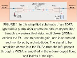
Thus, the first amplifiers available to propel the communications network industry into the frenzy we see today were EDFAs working in the C-band (see Fig. 1). The gain in an EDFA is the result of stimulated emission of photons from an excited population of Er+ ions within the fiber. The usable gain of typical erbium-doped fiber falls between 1530 and 1560 nm, which is why the C-band falls in that window. An effective EDFA, however, requires other components, such as various pumping lasers, pumping schemes, isolators, filters to redirect unused pump light, gain-flattening filters to make the gain more uniform across the usable band, and the correct couplers to get the signal from one end to the other.
Boosting performance
Much of the research and development on C-band EDFAs in recent years has focused on ways to flatten gain, increase power, improve vital parameters such as noise figure, and improve the capacityor number of dense wavelength-division-multiplexed (DWDM) channelsthat an amplifier can handle. Because of the rapidly growing demand for bandwidth, a major push today is delivering amplifiers that work in the longer-wavelength band (L-band) from 1563 to 1610 nm.
At first glance, the intrinsically lower gain presented by the EDFA in the L-band poses a problem. However, by using longer lengths of fiber and band-selecting filters to reject C-band signals, gain similar to that achieved by a C-band EDFA is possible. Care must be taken in this situation to address the problems generated by longer-wavelength amplifiers. The loss in the fiber is greater simply due to the length, and amplified spontaneous emission (ASE) can also become a problem in the amplifier.
These disadvantages can be contrasted with the advantage of working away from the zero-dispersion wavelength of the fiber. Most single-mode fiber used in communications networks is dispersion-shifted fiber designed for use at 1550 nm. However, by making the zero-dispersion wavelength 1550 nm (that is, non-zero-dispersion-shifted), undesirable nonlinear effects within the fiber (such as four-wave mixing, self-phase modulation, and stimulated Brillouin scattering) are generated. Moving over to the L-band reduces nonlinear effects.
According to leaders in amplifier development, this year is the year that L-band amplifiers will begin to appear in DWDM applications. Among the options for network designers will be the ability to use the wavelength range from 1563 to 1610 nm. In many of these situations, the L-band capability will be added to existing C-band capability using combiners and bandsplitters so that certain bands only go to the appropriate amplifier.
Evaluating alternatives
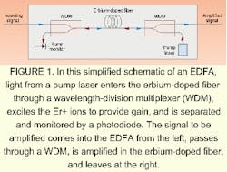
While most of the success in optical amplifiers has been enjoyed by EDFAs, the concept of using stimulated Raman scattering to amplify optical signals actually came before the EDFA concept. Stimulated Raman scattering is a physical phenomenon in which the pump photon is converted into an optical phonon and a lower-frequency photon. When the pump power is high enough, the incoming signal stimulates the process and provides signal amplification (see Fig. 2 on p. 74).
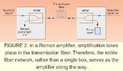
Raman amplifiers did not realize the same success as EDFAs mainly because the process requires very high pump laser power. Such high-power lasers have only recently become available. Now that the fundamental power problem has been solved, many groups are working to develop viable Raman amplifiers. Expanding the total bandwidth of fibers will require combining many of the technologies highlighted here. In addition, fiber dopants such as Er3+, thulium, and ytterbium are being explored. So-called hybrid amplifiers that combine two technologies also are showing great promise (see Fig. 3 on p. 74).
In addition to work in the 1525-1610 nm wavelength range, new fiber technology such as All-wave fiber (Lucent Technologies; Holmdel, NJ) and LEAF fiber (Corning Incorporated; Corning, NY) will allow expansion into other wavelength regions. Allwave fiber eliminates the absorption of the water peak between 1350 and 1450 nm, while LEAF fiber allows higher powers. Each of these fibers enables different technologies. Eventually, the entire range from 1280 to 1625 nm may be open for use in communications systems, which will expand the present 35-nm window to 345 nm!
Of course, by that time, we'll have invented so many new uses for the bandwidth that 345 nm won't be wide enough.
Stephen C. Bennett is product marketing manager at ILX Lightwave Corp. Photonics Test and Measurement Instrumentation, 4665-1 Nautilus Ct., Boulder, CO 80301; e-mail: [email protected].