One thing that living organisms do much better than machines is move around. A fly with a microscopic brain has no trouble navigating a three-dimensional (3-D) path, but a robot guided by a fast computer still has great difficulty following a simple path. The difficulty always has been in using landmarks to locate the robot's position accurately.
Now, recent improvements in laser rangefinding and in the techniques used to interpret visual data may finally allow robots to move effectively on their own. These advances may fuel a large new market for laser scanners and rangefinders, while opening up new applications for robotics in the home, the factory, and even out in the field.
From two- to three-dimensional systems
Currently, the main application area for laser machine vision lies in inspection systems, most involving two dimensions with no range information. Here, lasers compete directly with other machine-vision systems, such as devices based on structured light (stripes of light) or charge-coupled-device (CCD) images. In two-dimensional (2-D) applications, the main advantage of lasers is their high resolution, which is typically 10 times finer than that obtainable with CCDs.
Lasers gain even more of an advantage in 3-D applications. Many inspection tasks require measuring parts to see if they are within tolerance. With structured light, range measurements needed for such tasks are obtained indirectly from the deviation in the light stripes, a process that is often inaccurate and easily confused by the variations of reflectivity in the environment. With lasers, though, a number of rangefinding techniques can achieve high accuracy at short to medium ranges.
The simplest technique, laser triangulation, is generally used at distances of up to a few meters. One drawback of triangulation is that it can be thrown off by specular reflection from a shiny surface, but this may soon become less of a concern. Working with researchers at CAItech Inc. (San Jose, CA), scientists at Huazhong University of Science and Technology (Wuhan, China) have developed an elegant software fix to the problem.1 To isolate the specular reflections, the program measures the number of points on the measured surface close to a given point. When the density of this data cloud is low, a spurious point is indicated, because the point at a specular reflection will stand out above the surface. The specular reflections can thus be easily isolated and eliminated.
At larger distances, either phase- or pulse-timing is used. Phase-timing measures the phase shift in the reflected beam due to the distance to the reflecting surface, while pulse-timing measures the time delay for a single pulse of light. To allow adjustment of the wavelengths involved, the laser beam is either amplitude- or frequency-modulated. In both cases, time shifts translate into distance, but phase-shifting generally applies to small differences in distance—on the order of a few wavelengths of the modulating frequency. Pulse-timing applies to larger changes and greater distances.
Finding the range
Locating a robot in space is often a more-complex process than traditional inspection applications. The general problem lies in locating the robot relative to a map of the area, which may either be "trained" into the robot or determined by the robot itself. Rangefinding to a given landmark, such as a wall, can provide location only in one dimension, so other cues or rangefinding in a second direction are needed for accurate location in two dimensions. (Robots don't fly, so a third dimension is unneeded). In addition, wider ranges of distance are required than for inspection problems, where the scanning environment is standardized.
Several approaches have eased these difficulties and made reliable guidance more feasible. First, researchers are working on improving rangefinding accuracy by extending the range of phase-timing methods. At Spain's Universidad Carlos III De Madrid, researchers demonstrated a two-frequency amplitude-modulated rangefinder with a continuous-wave laser modulated at both 60 and 2 MHz.2 Because the phase shift can be measured for both modulations, the 2-MHz signal provides a maximum unambiguous range of 73.5 m, while the 60-MHz signal provides accuracy to less than a centimeter.
A novel modification of such rangefinding methods uses both frequency modulation and the self-mixing effect. The self-mixing effect occurs when laser light that reflects off an external surface is allowed to re-enter the laser cavity, causing interference effects. Simple self-mixing tends to act like an interferometer, with distance measurement repeating periodically within a range of only a wavelength of light. Now, however, Eric Gagnon of Spar Aerospace Ltd. (Brampton, Ontario, Canada) and Jan-Francis Rivest of Nortel Wireless Systems (Ottawa, Ontario) have devised a frequency-modulated system that gives an absolute range measurement.3
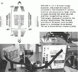
As the frequency of the laser is modulated through a ramping cycle, the power fluctuates in response to the external cavity formed by the reflecting surface, abruptly peaking when a resonant mode occurs. The difference in frequency between any two adjacent resonances corresponds to the frequency of the fundamental mode of the cavity and thus provides the absolute distance to the object. Because the same laser diode produces the laser signal and detects the return signal, there is no need for separate CCDs. Using a 30-Hz ramping cycle and carefully maintaining the temperature of the laser to within 0.001°C to avoid spurious amplitude variation, the Canadian team obtained range accuracies of less than a millimeter at a distance of 55 cm (see Fig. 1).Guiding the robot
For robot guidance, rangefinding alone is usually inadequate. First, ranging with a single laser only gives the robot's position in the direction that it is pointing and not perpendicular coordinates. Second, range data may not provide enough feedback for a robot to find an important landmark that has low relief, such as a closed door. One option combines conventional machine vision based on intensity measurements with rangefinding.
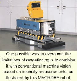
A European project is having success with this combined approach. In work performed by Jose Neira and Juan D. Tardos of the Universadad de Zaragoza (Zaragoza, Spain), Joachim Horn of Siemens AG, and Gunther Schmidt of Technische Universitat (both Munich, Germany), a MACROBE robot was equipped with a laser scanner that returned both range and intensity data (see photo at top of this page). Processing this intensity data produced vertical edges that were used to determine position relative to the robot's direction of motion.4
The robot uses both the range and the intensity data, with its vertical edges, to determine its position relative to a programmed map of the area. With the vertical edges, the program uses an iterative technique to match pairs of edges to the map. Once the angle of vision to a pair of edges is determined, the position of the robot can be calculated by triangulation. These data are then used to improve the position estimate derived from the range data.
The experimenters tried guiding the robot first with the range data, then with the intensity data, and finally with a combination of the two. As expected, the combined results gave the best precision, allowing an uncertainty of only 10 cm in position and 0.15° in orientation. Each step of the position-finding cycle takes only a second, allowing the robot to safely progress at reasonable rate.
Because a priori maps of an area are costly to program and may contain inaccuracies, the European team believes that future versions of the MACROBE system may be able to build their own maps of an area as they navigate it. If successful, these navigational devices have the potential to fuel more-widespread use of mobile robots for cleaning, supply, and parts delivery, and other tasks in hospitals, offices, and perhaps even homes.
REFERENCES
- D. Yang et al, Proc. SPIE 3652, 30 (Jan. 1999).
- S. Pereze et al., Proc. SPIE 3626, 48 (Jan. 1999).
- E. Gagnon and J. F. Rivest, IEEE Trans. Instrumentation and Measurement 48, 693 (June 1999.
- J. Neira et al., IEEE Trans. Robotics and Automation 15, 76 (Feb. 1999).
About the Author
Eric J. Lerner
Contributing Editor, Laser Focus World
Eric J. Lerner is a contributing editor for Laser Focus World.

