Waveguide Optics: Novel alumina optical waveguides have very low loss in the blue and near-UV
Films of alumina were grown on bare silicon and on silicon dioxide (SiO2) on silicon with growth-process parameters optimized for defect-free growth, producing a film with refractive index of 1.65 at 633 nm and 1.72 at 260 nm. The researchers say that, although the refractive index could be boosted by high-temperature annealing, this would change the alumina to a polycrystalline form with high optical loss (>20 dB/cm).
Plasma-enhanced chemical vapor deposition (PECVD) SiO2 was patterned on top of the alumina and the alumina plasma-etched, and then a layer of PECVD SiO2 was added to clad the waveguides. The researchers fabricated waveguides with widths of 400 to 600 nm and sidewall angles of about 80° that are single-mode for all test wavelengths (371, 405, 419, and 458 nm) except for the 600 nm width at 371 nm, which is multimode.
Reducing scatter is important
It is important to minimize scatter in waveguides used in the blue and near-UV, as light scatters strongly at short wavelengths. The relatively low refractive index of alumina (2.0–2.2) in comparison to that for other materials that have been experimentally used for short-wavelength waveguides results in physically larger waveguides, leading to weaker sidewall scattering for equivalent sidewall roughness.
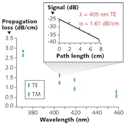
Light was coupled into and out of the waveguides via either 40X microscope objectives or direct butt-coupling of a fiber to the waveguide end. The researchers measured propagation loss of the alumina waveguides by comparing two waveguide structures and step-by-step cutting back the length of one of them. Loss was found by doing a linear fit of the log of the output power vs. waveguide length.
For the 405, 419, and 458 nm test wavelengths, the 600-nm-wide waveguide exhibited the lowest loss. For the 371 nm wavelength, the 500-nm-wide waveguide had higher transmission than the one with 600 nm width, which exhibited multimode operation at that wavelength. The TM modes have lower losses than the TE modes—for example, at 405 nm, losses were 1.23 dB/cm for TM and 1.61 dB/cm for TE (see figure).
The 600 nm width exhibited the lowest loss for λ = 405, 419, and 458 nm, and the 500 nm width exhibited the lowest loss for λ = 371 nm (because of multimode operation in the 600 nm width).
In addition, a ring resonator with a 500 nm waveguide width and a 90 µm radius was fabricated. Measured via the cutback method, the loss at 405 nm for the TE mode was 1.91 dB/cm (TM mode loss was high enough that the resonator did not achieve resonance for this mode). A mode-hop-free tunable 405 nm laser source was used to find resonance and a quality factor (Q) of 470,200 was measured at 405 nm.
Propagation loss in the ring resonator measured by a different method (ellipsometric index dispersion data and a 2D mode solver) resulted in a 2.35 dB/cm loss value. The discrepancy between this measurement and the one resulting from cutback measurements is because of radiative bend loss and increased mode intensity at the scattering sidewalls, the researchers say.
The researchers say that, because their measurements showed that the waveguide loss was likely dominated by scattering, it should be straightforward to further reduce loss via improved fabrication.
REFERENCE
1 G. N. West et al., arXiv:180800429v1 [physics.optics] (Aug. 1, 2018).
About the Author

John Wallace
Senior Technical Editor (1998-2022)
John Wallace was with Laser Focus World for nearly 25 years, retiring in late June 2022. He obtained a bachelor's degree in mechanical engineering and physics at Rutgers University and a master's in optical engineering at the University of Rochester. Before becoming an editor, John worked as an engineer at RCA, Exxon, Eastman Kodak, and GCA Corporation.