Inorganic electroluminescent displays aim to displace CRTs
The term "electroluminescence" describes the phenomenon of light emission from a material in the presence of an electrical field. Many variations of electroluminescent (EL) displays have been tried since the 1940s as the technology has fallen in and out of favor. Some of these variations have achieved limited commercial success in niche applications, but one new variation—the thin-film phosphor, thick-film-dielectric EL display—shows promise for making EL a mainstream flat-panel-display (FPD) technology in the near future, a foundation for a no-compromise hang-on-the-wall TV.
One hallmark of the EL display is its simple structure compared to other FPD types such as liquid-crystal displays (LCDs) and plasma-display panels (PDPs), the latter also known as gas-discharge displays. The EL display is a straightforward "sandwich" of layers deposited between two sheets of a substrate, typically glass or ceramic, on top of a matrix of X-Y electrodes.
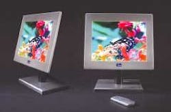
The self-contained EL sandwich consists of light-emitting phosphor layers surrounded by dielectric layers and a grid of perpendicular electrodes. The LCDs, in contrast, require a light source, a light-distribution system, multiple polarization films, a transistor array, and heavy color filtering. As for PDPs, they require a complex barrier structure to contain the plasma gas within specific display cells for pixel definition and, moreover, necessitate an internal vacuum. As their names imply, the LCD is based on a liquid mixture and the PDP on a gas while the EL display is an all-solid-state technology based on solid phosphors. The solidity and simplicity of the EL display leads to its ruggedness and insensitivity to environmental conditions, as well as the potential for high yield and low cost (see Fig. 1).
null
Like other luminescent devices, EL displays emit photons when the electrons in their solid phosphors, energized by an electrical field, return to a lower energy state. Despite this similarity, however, inorganic ELs have a unique operation that addresses difficult applications. The most common phosphor compound used in ELs is zinc sulfide with a manganese dopant or "activator" (ZnS:Mn). In this compound, hot electron impact ionization of the activator comes into play.1 This type of excitation mechanism is relatively insensitive to a broad range of environmental parameters, a characteristic that leads to some of the EL performance advantages.
An EL taxonomy
Two other types of displays that make use of the phenomenon of electroluminescence are the light-emitting diode (LED) and the organic light-emitting diode (OLED). The OLED, a newcomer to the realm of FPDs, uses a light-emitting plastic as its light-generation medium, either a monomer or polymer. The respective short and long molecular chains of these materials both contain carbon atoms and are, thus, called "organic," which differentiates them from the traditional "inorganic" (noncarbon-based) class of displays including LED and EL. The LED uses a single-crystal semiconductor material as its light-emitting component, while the EL uses polycrystalline (thin-film) or powdered (thick-film) phosphors.
Electroluminescent displays break down into a simple matrix of AC and DC types, based on the nature of the driving voltage; and thin-film and thick-film types, based on layer thickness. No DC variety has ever reached production, but both thin-film and thick-film AC varieties have found their niche. Because of their extremely thin profile, simple construction, and uniform light emission, thick-film AC EL devices have found a good market in backlighting applications such as planar lamps for keypads and small LCDs. Thin-film AC EL (generally known as TFEL) devices have succeeded as information displays in some military, medical, industrial, and transportation niches—applications in which LCDs have difficulties with temperature range, response speed, or other performance requirements.
Thin-film EL
In the past 30 years, the effective lifetime of TFEL displays was extended and their brightness and contrast were boosted, while the advent of large-scale-integration ICs made feasible the manufacture of highly matrixed displays with the many rows and columns needed to handle high information content. Some of the first portable computers (precursors to today's laptops) used monochrome yellow TFEL displays. Nevertheless, despite incremental improvements to TFEL, the technology is still relegated to niche applications for its strengths of good image quality, wide viewing angle, fast response time, broad temperature range, inherent ruggedness, and temperature insensitivity.
Several major limitations of TFEL technology have yet to be overcome, including relatively limited brightness, the lack of full-color capability, and difficulty in scaling to large sizes. Relatively high cost has also been a major deterrent. The thin dielectric and phosphor layers used in TFEL displays are prone to pinhole defects and particulate contamination during manufacturing. This introduces stringent and expensive clean-room requirements to the manufacturing process that reduce manufacturing yields.
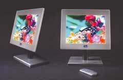
Replacing the thin-film dielectric of TFEL with a thick-film, high-dielectric-constant (K >1000) dielectric material overcomes the traditional limitations of TFEL without losing its advantages. The dielectric layer contains a combination of materials 10 to 20 µm thick, 20 to 100 times thicker than the traditional dielectric. Dielectric strength is improved, as well as resistance to contamination, electrical breakdown, and manufacturing defects. Simple and inexpensive printing and firing tools and processes can be used for dielectric deposition, rather than the expensive vacuum-deposition equipment and processes required by TFEL (see Fig. 2).
null
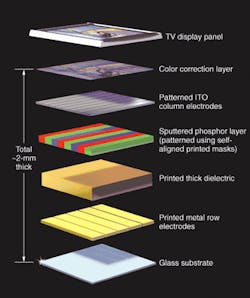
Further, a thick dielectric gives a substantial boost to performance. A high dielectric constant increases electron density, electron-injection efficiency, and light outcoupling for EL technology to new levels. Using the same thickness of the same ZnS:Mn phosphor, a thick-dielectric EL display (TDEL) has approximately five times the brightness of a traditional TFEL display, as well as much higher efficiency.
In addition, since the voltage drop across a thick dielectric is far lower than that for a thin dielectric, the TDEL can use thicker phosphor films than TFEL displays, increasing brightness even further—by as much as a factor of two for some phosphors. With a thick-film dielectric as a foundation, the challenge lies in developing a suite of thin-film polycrystalline phosphors that can efficiently generate the red, green, and blue light components required to provide full-color imaging with rich, saturated colors. Worldwide research on thin-film phosphors focuses primarily on narrowband phosphors for generating the primary colors such as binary and ternary sulfide and oxide phosphors (see Fig. 3).
null
New phosphors and old
The brightness capabilities of full-color TDEL displays have grown from 20 cd/m2 in 1997 to 350 cd/m2 in mid-2001—in large part due to the development of unique thin-film phosphors. Recently, we achieved red, green, and blue phosphors capable of supporting a luminance reaching 500 cd/m2.
In 2000, development of second-generation (G2) blue and green phosphors made it unnecessary to depend on multiple layers of different phosphor compounds or partial patterning technique. The performance of these G2 phosphors was sufficient for TDEL displays to use a fully patterned structure for the first time, with a discrete phosphor compound for each of red, green, and blue pixel sites.
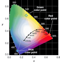
With new G2 blue and green phosphors plus old workhorse ZnS:Mn for red, thick-dielectric EL displays achieved a chromaticity range equivalent to that of a CRT in early 2001, meeting the color standards of the European Broadcast Union and providing a 350-cd/m2 brightness level. The most important phosphor development was for the blue, which used breakthrough europium-doped barium aluminum sulfide, BaAl2S4:Eu. Today this blue, together with a new green based on simple zinc sulfide with a terbium dopant (ZnS:Tb) has produced luminance and efficiency sufficient for TV applications.
null
Two variations on a third-generation green phosphor reported this year will enable TDEL displays to reach even higher performance levels. Both are europium-doped calcium thioaluminate compounds: CaAl2S4:Eu and MgxCa1-x Al2S4:Eu. The addition of manganese to the latter boosts brightness and reduces the annealing temperature required to crystallize phosphors, important for scaling the technology to large sizes (see Fig. 4). Design and process parameters require validation at every stage of development as new variations attempt to achieve the no-compromise hang-on-the-wall TV.
REFERENCE
- L. E. Tannas Jr., Flat Panel Displays and CRTs, Van Nostrand Reinhold (1985)
Don Carkner is the vice president of product planning at iFire Technology, 15 City View Dr., Toronto, Ontario, Canada M9W 5A5; e-mail: [email protected].