Researchers at Iguana Robotics (Mahomet, IL) and Johns Hopkins University (Baltimore, MD) have demonstrated a single-chip analog image-processing system that can acquire color images, perform color segmentation, transform image color space, create color profiles, and match acquired images with templates.1 Because such devices are very small, low in power consumption, and inexpensive to manufacture compared to their digital counterparts, their applications should be many, including microrobotics, personal computers, and toys that "see."
This work, presented to the IEEE International Solid-State Circuits Conference in San Francisco in February, is an extension of research done at California Institute of Technology (Cal Tech; Pasadena, CA) in the mid-1990s. The Cal Tech team showed that it was more appropriate to use hue-saturation- intensity (HSI) color space rather than the red-green-blue (RGB) coordinate system, and demonstrated an analog circuit that could translate between the two. Their approach showed how the HSI color space, which is most commonly used to understand human vision system, produces feature sets that are better for image segmentation: breaking the image into individual sections that can be considered a discrete object and then pattern-matched. Their analysis showed that, in some circumstances, HSI-based coordinate systems are less variant to some changing lighting conditions—such as shading, highlighting and transparency—than their RGB counterparts.

The Iguana Robotics chip consists of a 128 x 64 (horizontal by vertical) array of imaging pixels, which sample RGB signals sequentially (using a color wheel in this prototype) and holding them for further use. Integrated with these detectors are mixed-signal electronics to perform the various processing steps. Processing is performed in blocks, the size and scanning patterns for which can be programmed in for a given application, the first step being the RGB-HSI transformation. This operation is performed by summing the RGB components to get intensity, subtracting the minimum of the normalized RGB values from this to get the saturation, and using an analog version of a lookup table to implement the equation for hue. This latter circuit also maps the RGB data into 36 hue intervals, each spaced 10° apart.
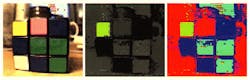
Once the color space has been converted, a profile of the image is created based on its HSI histogram. The color space is divided into several discrete areas and the number of pixels within each chunk counted (see figure). In the learning phase, image blocks of particular interest are identified and the camera takes this information, develops the appropriate profile, and stores it in an array of static random-access memory cells. In the pattern-matching phase, the block-pattern profiles from the image currently being scanned are compared with the templates for these stored regions of interest and the error codes generated used to find the best match. The researchers say that, using the RGB filter technology commonplace with conventional color cameras, the footprint of their imaging and recognition will be tiny: their current device has an area of less than 0.25 cm2.
REFERENCE
1. Ralph Etienne-Cummings et al, IEEE Int. Solid-State Circ. Conf., San Francisco, CA, 4 (February 2002).
About the Author
Sunny Bains
Contributing Editor
Sunny Bains is a contributing editor for Laser Focus World and a technical journalist based in London, England.