Inspired by the compound eyes of insects, a group of Japanese researchers has developed a technique for building large cameras with small optics. The new apparatus is a tradeoff between hardware size and the additional computational overhead required to accurately combine subimages into a single high-resolution composite, and is made possible through a collaboration between eight academic and industrial establishments based mainly around Osaka. The hope for the new technology is that it will allow use of high-resolution cameras in places that could not accommodate large lenses—mobile phones and personal digital assistants being obvious commercial candidates. Space-borne systems, in which weight is at a premium, may also eventually benefit from this type of approach.
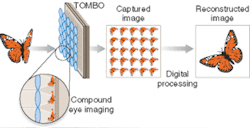
Named TOMBO (thin observation module by bound optics) by its inventors, the new system differs from an insect eye in that each lens does not map onto just one pixel but onto many, creating a low-resolution image of the object being captured (see figure). Because the size of the camera array behind the lenses is still large, the amount of image information captured is the same as it would be for a conventional system—the difference is the order in which the pixels are arranged. The challenge for the development team was to find ways to re-order the pixels while taking account of imperfections in the hardware.
Several issues have to be considered during reconstruction.1 First, the images must be normalized to correct for shading effects caused by the separating walls used to prevent crosstalk. Essentially, these mean that the central area of each subarray receives more light than the outer margins do. This normalization is done by performing a calibration step at the beginning with all-black and all-white images and using the variations in these images to correct the raw data.
Next, the subimages need to be identified (which is simply done by looking at the pixel addresses) and the subjects registered against each other so that they can be mapped and combined into the new image. The team has come up with two methods of doing this, one involving cross correlation and the other a more-complex maximum-likelihood method. The former uses the shift invariance of the Fourier transform to center each subimage on the same point, which in turn centers each subimage pixel on a composite-image pixel. The latter is more complex and compensates for deformations cause by optical misalignment as well as spatial shifts. Once the mappings have been calculated and performed, blank pixels can be filled in using interpolation. Finally, the entire image is filtered to compensate for the calculated point-spread function of the system.
Color versions
One of the advantages of this type of system is that it turns out to be incredibly easy to adapt to color.2 One obvious way to do this is simply to use a color camera as the main array. There is another option, however, that is potentially even easier to manufacture—use a color filter under each imaging subunit. Because the pixels are to be rearranged anyway, they can start out with pixels being grouped together by color. The team has performed both of these experiments and found that each had its own advantages, as well as a very different angle of view. This has suggested to researchers that they should be able to design the angle of view into future systems without changing device parameters. Filtering by imaging subunit seems to be better for general-purpose imaging because it has a long observation distance, whereas using pixel-based separation is better for more precise spectral measurement. The researchers say that based on this idea, they should be able to construct a compact multispectral imaging camera.
The group is working on several approaches to improve the system, on both the hardware and the processing side. Amplification of noise is one issue being addressed, as are the problems of microlens shape and misalignment, which are sources of noise in the first place.
REFERENCES
- Y. Kitamura et al., Applied Optics 43(8), (March 10, 2004).
- J. Tanida et al., Optics Express 11(18), (Sept. 8, 2003).
About the Author
Sunny Bains
Contributing Editor
Sunny Bains is a contributing editor for Laser Focus World and a technical journalist based in London, England.
