Laser radar signals the civilian sector
Laser radar signals the civilian sector
Evaluating shape rather than reflection provides range-based image-mapping and object-recognition capabilities for civilian as well as military applications.
Gary W. Kamerman
Although police laser-radar systems for traffic enforcement and laser-based surveying instruments are now commonplace, many people still believe that laser radar is nothing more than exotic military technology. While numerous military applications for this technology exist, the number of civilian uses is steadily climbing. The Laser Radar Technology and Applications conference at the SPIE AeroSense Symposium (Orlando, FL) held this month highlights laser radar as perhaps the next major growth area for optical sensing and machine vision.
In all imaging applications, the fundamental problem is how to identify a target based on an appearance (signature) that varies with surface, lighting, environmental conditions, viewing angle, and percent exposure (see "Remote imaging seeks target in clutter," p. 82). Faced with such challenges, even a human observer can be fooled. Automated imaging systems require significant computing power and time, and even the most sophisticated pattern-recognition algorithms and imaging systems are prone to error.
By making direct measurements of target shape and position, laser radar bypasses the data-processing bottleneck. Unlike appearance, shape is fundamental to the identity of an object. Measuring the shape and then matching it to a three-dimensional (3-D) model is a reliable approach to object identification; moreover, the process is not computationally intensive.
Object recognition
To measure shape, a typical laser-radar system sends a short (1-ns) pulse of light out toward a target. The system detects the return of the reflected light, recording time of flight. Scanning optics step the transmitting beam to a new point in the scene being imaged, and the laser-radar system sends another pulse. By scanning the beam in a raster pattern, such a system can generate an angle-angle-range (AAR) image similar to an angle-angle-intensity television image.
A wide variety of lasers can be used, including neodymium-doped yttrium aluminum garnet (Nd:YAG), thulium-doped YAG (Tm:YAG), carbon dioxide (CO2), and gallium aluminum arsenide diode lasers. These lasers may also use a variety of modulation formats, but the operation of the system is fundamentally the same.
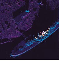
The AAR image is a map of the geometry of the interrogated scene in spherical coordinates and as such can be transformed into any other coordinate system. For example, an AAR image of a ship acquired from the side can be converted to Cartesian coordinates and presented from a top-down perspective. This format simplifies 3-D correlation of the data with a geometric models of various ships to identify the target (see Fig. 1).
This same form of geometric transformation can be used for topographic site surveys or for mapping power and telephone lines (see Laser Focus World, April 1995, p. 34). In an AAR image, the data can be presented in a height-above-ground rendering, clearly showing the shape of details such as buildings, bridges, and towers.
The shape-recognition approach does not suffer the problems inherent in passive-imagery-based automatic target recognition. For example, partial obscuration of the target results in lost data, analogous to data missing from the back side of the target. Because the geometric reference model includes all sides of the target, missing information from the front or the back of a coordinate-transformed image simply reduces the height of the correlation function, it does not shift the peak location.
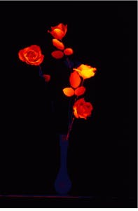
Comparison of the resulting images when flowers in a vase in front of a floral still life are imaged by a laser-radar system and a conventional camera demonstrates how range-based imaging can separate a targeted object from reflective clutter (see photo, p. 81).1 The color photograph captures a confusion of blossoms. In the laser-radar image, however, the geometry of the real vase and flowers is immediately obvious and distinguishable from the flat geometry of the painting.
Applications
The military problem of finding the tank in the trees shows up frequently in civilian robotic assembly operations. The problem is bin picking, rather than search and destroy, but the basic issue is still one of locating a single, randomly oriented object in the midst of clutter. In most robotic assembly applications, the clutter consists of other nearly identical parts and objects put in the bin by mistake. Generally, the robot is trying to pick up the part on top of the pile, then checking to verify that it is the right one.
Misbinned objects are usually quite similar to the ones that belong there, otherwise the fallible human using only passive imagery would not have been fooled into putting it into the wrong pile. To identify subtle shape differences between these misbinned items and the correct parts often requires 3-D data. Most industrial machine-vision systems use structured light or stereoscopic vision to extract 3-D measurements of shape and location. Humans seem to function fairly well with stereo passive imagery, but, unless the problem is carefully constrained, machines still have trouble working out the details in anything ap proaching real time.
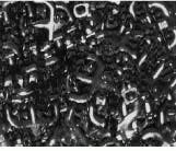
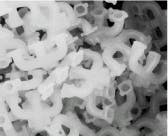
Because laser radar can identify geometric features in spite of reflective clutter, the technology is a good ap proach for parts selection. At a major automotive assembly facility, a laser-radar system manufactured by Perceptron Corp. (Farmington Hills, MI) identifies exhaust manifolds in a bin. The manifolds are difficult to distinguish with conventional machine vision because of the reflective metal surfaces. In the rangefinding image, however, individual parts are clearly defined (see Fig. 2).
A laser-radar system collects geometric data in three-dimensional space, so the scan does not need to follow a conventional raster pattern nor does it need to be highly stabilized. An imaging bathymetry system developed by the Swedish Defense Research Establishment (Linköping, Sweden) uses several scan patterns to measure water depth from a moving aircraft. The bathymeter is a two-color system composed of a Nd:YAG laser operating at 1064 nm (fundamental) and 532 nm (frequency-doubled). The green pulses penetrate the water, while the infrared pulses reflect off the surface. Water depth is determined by the difference in arrival time between the surface return and the pulse reflected from the bottom of the ocean.
By scanning the laser-radar beam from side to side as the aircraft moves forward, the bathymeter generates a strip map of the bottom contours that reveals shipping-channel profiles and locates underwater obstructions. As long as the orientation of the laser radar is known for each pulse, the knowledge of the geometric location of the bottom return is not affected.2
Reducing cost
Although military and nonmilitary applications for laser radar have grown steadily, cost is still a major barrier to its widespread adoption. With cost-reduction efforts, this situation is beginning to change. Raytheon (Tewksbury, MA) and FastMetrix (Huntsville, AL) both have developed coherent CO2 laser-radar systems for less than $200,000. Designed for the US Army Multiple Launch Rocket System (MLRS), the Raytheon system uses a focused beam to map the wind speed at a distance of 100 m. Raytheon is gearing up to manufacture approximately 1000 of these systems for MLRS, which is reportedly a record for the largest production run of coherent laser-radar systems.3
The FastMetrix system is a diagnostic instrument that incorporates a laser to measure high-speed linear velocity and dynamic transients. It has been used to monitor the interior ballistic motion of projectiles fired by advanced gun systems; conventional diagnostics are inadequate to the task.
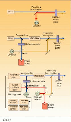
In both of these systems, cost was reduced through the use of a common-path homodyne (CPH) receiver architecture. This innovative approach reduces the parts count in CW laser radar systems by eliminating the normally separate local-oscillator beam path found in conventional heterodyne and homodyne systems. These conventional systems use multiple beamsplitters and lenses to fold part of the transmitted beam into a local oscillator, necessitating tight assembly and alignment tolerances (see Fig. 3).
In CPH systems, a deliberate internal reflection in the transmitter beam path scatters a controlled amount of light back into the receiver optics, which form the cavity for the local oscillator. This method reduces the parts count and the cost of the optical and optomechanical components of the system.
Elsewhere, engineers are attempting to cut costs through the use of alternate technologies and architectures. Diode lasers and diode-pumped solid-state lasers, for instance, may serve as economical sources for rangefinding systems. Probably the biggest gains in cost control have been made in the area of scannerless systems. As demonstrated by the number of papers scheduled for the SPIE AeroSense Laser Radar conference,4-6 this is an active area of research.
Scannerless systems are analogous to staring focal- plane arrays; the laser illuminates the entire scene simultaneously, while the staring detector array collects the return signals. These types of systems reduce cost by eliminating the scanner and scanner-control elements. Because the images are collected in much shorter periods of time, the scannerless systems also can have relaxed platform-stabilization tolerances. This last is an important point; many system developers consider platform stabilization to be as difficult and expensive as sensor development.
Future advances probably will continue the trend to develop more reliable, economical systems rather than pushing to continually higher levels of performance. The one exception to this direction is likely to be in the area of laser-radar chemical detection based upon differential-absorption lidar and Raman scattering. Here significant advances in both performance and cost control are necessary to bring the technology to its full potential. n
REFERENCES
1. L. J. Van Wezel, H. K. Roberts, and D. Zuk, Laser Radar Technology and Applications Conference, SPIE AeroSense Symposium (Orlando, FL), paper #2748-01 (April 1996).
2. O. K.Steinvall, U. C. Karlsson, and K. R. Koppari, Laser Radar Technology and Applications Conference, SPIE AeroSense Symposium (Orlando, FL), paper #2748-02 (April 1996).
3. C. E. Harris, Laser Radar Technology and Applications Conference, SPIE AeroSense Symposium (Orlando, FL), paper #2748-09, (April 1996).
4. H. N. Burns, T. D. Steiner, and D. R. Hayden, Laser Radar Technology and Applications Conference, SPIE AeroSense Symposium (Orlando, FL), paper #2748-03 (April 1996).
5. J. T. Sackos, Laser Radar Technology and Applications Conference, SPIE AeroSense Symposium (Orlando, FL), paper #2748-04 (April 1996).
6. R. D. Richmond and R. Stettner, Laser Radar Technology and Applications Conference, SPIE AeroSense Symposium (Orlando, FL), paper #2748-05 (April 1996).
Color photograph of flowers in a vase backed by a floral painting shows a nearly undifferentiated profusion of blooms (left). The same composition imaged with laser radar clearly distinguishes the vase and real flowers from the background (right). To create the range image, 1 million measurements were made with a precision of about 2 mm.
FIGURE 1. Because laser-radar images are acquired in spherical coordinates, they can be transformed into other coordinate systems, viewed from different angles, and correlated with three-dimensional target images for shape recognition. Range-based image (middle) of the side of the USS Alabama (top) is converted to a top view, clearly showing the vessel shape (bottom).
FIGURE 2. With conventional machine vision, shiny metal exhaust manifolds are difficult to distinguish (left). If the scene is imaged with laser radar (right), individual parts are readily distinguished and their proximity to the sensor is calculated.
FIGURE 3. Common-path homodyne Doppler laser radar (top) contains fewer elements than a conventional homodyne (middle) or conventional heterodyne (bottom) system, making this an economical approach.
Remote imaging seeks target in clutter
Laser-radar research began in the military, where the fundamental imaging problem is relatively straightforward: how do you find the tank hidden in the trees? This may oversimplify the problem a little, but it encompasses most of the issues associated with military imaging.
Passive sensors such as television, thermal imagers, or forward-looking infrared systems detect only noncritical target features. Such features are just the intensity patterns generated by reflection of external radiation and the emission of self-generated thermal radiation. They are not fundamental to the object and are at best noncritical image artifacts. These features can be modified (camouflaged) without changing the function of the target; a pink tank with yellow spots may appear quite different from an olive-green version, but it is still a tank. Furthermore, the thermal image of a wet tank differs from that of a dirty tank, which differs from a tank that has been sitting in the sun or one with a running engine.
Other complications increase the difficulty of target detection. The appearance of an object, or signature in military parlance, is aspect and orientation dependent. A tank viewed from the side looks considerably different than the same tank viewed from the front or from the top. Tanks are a particularly knotty problem because their signature is also dependent upon conformation (the turret turns) and configuration (the military has a tendency to hang other "stuff" on tanks).
Even if the target does not change orientation, configuration, or color, the signature is still sensitive to a wide range of illumination artifacts such as shadows, glints, sun angle, and so on. The whole problem of recognizing a target changes again if even a small portion of the object is hidden, say by another target, or a bush, or a tree.
Sophisticated image-processing algorithms have been developed to automatically find targets hidden in passive imagery. Most don`t work very well or function only under a very narrow set of conditions. The ones that do work require enormous computational power. A critical issue is that all of these algorithms are still prone to false alarms, mistaking other objects (such as warm rocks, oil drums, or cows) for tanks.
G. W. K.
GARY W. KAMERMAN is chief scientist at FastMetrix Inc., 906 Sommerset Rd., Huntsville, AL 35803, and laser programs manager at Nichols Research Corp., 4890 W. Kennedy Blvd., Ste. 475, Tampa, FL, 33609; e-mail: [email protected].
