National Ignition Facility design focuses on optics

National Ignition Facility design focuses on optics
State-of-the-art optical fabrication, metrology, and coating techniques are needed to meet specifications for 8000 large and 30,000 small precision optical components in NIF.
William J. Hogan, L. Jeffrey Atherton, and Jeffrey A. Paisner
ometime in the year 2002, scientists at the National Ignition Facility (NIF) will focus 192 separate high-power ultraviolet laser beams onto a tiny capsule of deuterium and tritium, heating and compressing the material until it ignites and burns with a burst of fusion energy. The mission of NIF, which will contain the largest laser in the world, is to obtain fusion ignition and gain and to use inertial confinement fusion capabili t ies in nuclear weapons science experiments. The physics data provided by NIF experiments will help scientists ensure nuclear weapons reliability without the need for actual weapons tests; basic sciences such as astrophysics will also benefit.1-3
To design, build, and operate the facility, Lawrence Livermore National Laboratory (LLNL) is leading a collaborative effort with Sandia National Laboratories (Albuquerque, NM), Los Alamos National Laboratory (Los Alamos, NM), and the University of Rochester Laboratory for Laser Energetics (Rochester, NY). The project currently involves more than 300 team members and 35 corporations, including Schott Glass Technologies (Duryea, PA), Hoya Corp. (San Jose, CA), Cleveland Crystals Inc. (Cleveland, OH), Tinsley Laboratories Inc. (Richmond, CA), Zygo Corp. (Middlefield, CT), Corning Inc. (Corning, NY), Eastman Kodak Co. (Rochester, NY), Spectra-Physics Lasers (Mountain View, CA), Optical Coating Laboratory Inc. (Santa Rosa, CA), and WYKO (Tucson, AZ). As of this writing, the NIF Title I engineering design, updating the original 1994 conceptual design, is nearing completion, with actual facility construction slated to begin in April 1997 (see Fig. 1).
The facility faces stringent weapons-physics user requirements demanding peak pulse powers greater than 750 TW at 0.35µm (only 500 TW is required for target ignition), pulse durations of 0.1 to 20 ns, beam steering on the order of several degrees, and target isolation from residual 1- and 0.5-µm radiation. Additional requirements include 50% fractional encircled beam energy in a 100-µm-diameter spot, with 95% encircled in a 200-µm spot. The weapons-effects community requires 1- and 0.5-µm light on target, beam steering to widely spaced targets, a target chamber accommodating oversized objects, well-shielded diagnostic areas, and elimination of stray light in the target chamber.
Beamline design
At the heart of NIF is 192 separate, identical flashlamp-pumped Nd:glass laser beamlines. Each beamline undergoes amplification and two levels of frequency conversion prior to converging on the tritium/deuterium capsule in the target chamber (see Fig. 2). A preamplifier module (PAM) delivers a 10-J temporally shaped pulse to a pinhole in a transport spatial filter (TSF); a Galilean telescope placed between the PAM and the TSF produces a converging cone of light that passes through the TSF pinhole and diverges to a 40 ¥ 40-cm square beam.
The beam propagates through the booster amplifier and relay optics. A Pockels cell switches the pulse into the main amplifier cavity, where it makes four passes though the gain medium. After the fourth pass, the pulse is switched out of the main amplifier cavity by means of a full-aperture Pockels cell to traverse the booster amplifier a second time before passing into the target area, where it is frequency-converted from 1 to 0.52 to 0.35 µm prior to hitting the actual target.
For ignition targets, each beamline must place 95% of its laser energy through a 600-µm spot in the center of the entrance hole of the target. The temporal shape of each pulse has a 15-20-ns low-power pedestal followed by a 3-ns (FWHM) high-power peak; together the 192 beamlines focus as much as 2.2MJ of energy on the target with a peak power of 600 TW. These figures represent the "redline" of the facility, a 20% design margin over the 1.8-MJ/500-TW requirement for ignition. A wide range of operational modes is available; for example, each beamline can have its own temporal pulse shape.
An adaptive optics system in each beamline will correct wavefront errors in the main pulse based on a low-power diagnostic pulse sent through the system prior to the main pulse. The full-aperture deformable mirror in each beamline is located at the far end of the main amplifier cavity. Wavefront correction is necessary to reduce spot sizes, reaching the increased output intensities required by the weapons-physics community; the new design improves wavefront correction over the conceptual design by increasing the number of actuators in each mirror from 23 to 39. As with all components of the laser, the deformable mirrors are located in line-replaceable units, to ease assembly and maintenance.
Amplifier configuration
The PAM has been conceived as a modular subassembly. An optical fiber carries a tiny, temporally shaped laser pulse from the master oscillator room to the PAM, which contains both regenerative and multipass amplifiers. The pulse circulates 12 times through the diode-pumped Nd:glass ring regenerative amplifier. On exit, the pulse passes through a serrated aperture that converts the round cross section to a square cross section; then a four-pass flashlamp-pumped Nd:glass laser boosts the millijoule output of the square aperture to more than 10 J per pulse at the TSF. In the PAM, the beams are also smoothed by spectral dispersion to the degree required by either direct or indirect drive targets.
The NIF main amplifier and booster amplifier are composed of identical Nd:glass laser slabs--11 slabs in the main amplifier for a single-pass, small-signal gain of 14.5 and seven slabs in the booster for a single-pass gain of 5.5. The configuration minimizes amplifier-Pockels cell interaction, space requirements, and polarizer damage threshold; it also simplifies alignment and reduces beam-quality degradation by more than 10% over the initial design. It is similar to the design of Beamlet, the single-beamline NIF prototype that demonstrated the required full-aperture performance in 1994 (see photo on p. 107).
The main amplifier consists of one 4 ¥ 12 array of beamlines in each of four laser bays. The arrays are further subdivided into 4 ¥ 2 bundles, a configuration that simplifies the cooling process, enhancing thermal uniformity and improving shot rate. It also eases assembly, activation, and maintenance of the laser and reduces technical risk. An amplifier development laboratory under construction will test the performance of amplifier modules; the modules scheduled for test in 1997 are very similar to the designs for the full-sized 4 ¥ 2 modules.
The NIF target area includes the beam transport lines, the final optics packages, the 10-m-diameter target chamber and all the target diagnostics. Twenty-four laser-beam ports spaced around the equator of the target chamber permit conversion to direct drive by moving 24 of the indirect-drive final optics assemblies (FOAs) or by later installation of an additional 24 FOAs, along with switchable turning mirrors. A large-diameter access port near the equator allows researchers access to insert large objects to be exposed to radiation.
The FOA design requires several optics, including transmission gratings to isolate the 0.35-µm light from residual 1- and 0.5-µm illumination. The grating design was tested in a subscale experiment and proven to be effective in efficiently disposing of the unwanted wavelengths without degrading the desired wavelength. It also allows more flexibility for other pointing and operating requests of the users.
Requirements for optics
A number of companies are involved in fabrication process development for the more than 8000 large and 30,000 small precision optics included in the overall NIF design, focusing on mass-production methods that will meet the specifications while lowering the unit cost. Prototype full-scale components are being assembled and tested to ensure meeting performance specifications in production models.
The NIF optical components include neodymium-doped phosphate laser glass; fused silica lenses, windows, and debris shields; electron-beam-deposited hafnia/silica multilayer coatings for mirrors and polarizers; potassium dihydrogen phosphate (KDP) crystals for the plasma electrode Pockels cell and second-harmonic generation; and deuterated KDP (KD*P) for third-harmonic generation. With a beamline clear aperture of 40 cm, the optics will range in size up to 45 ¥ 80 cm.
Optical surface specifications are comparable to those of Beamlet with one important exception: mid-spatial frequency (1 to 10 mm-1) ripple is defined by a power spectral density function (PSD; see Fig. 3). Beamlet experiments and concurrent propagation modeling have shown that controlling millimeter-scale ripple is vitally important to minimize nonlinear growth and near-field modulation. Because many of the deterministic processes used to polish NIF optics have the potential for inducing this ripple, the use of PSDs and appropriate metrology is vital. Phase interferometry will be used at two apertures, 61 cm and 15.3 cm, to measure full-aperture and millimeter-scale features, respectively.
The current specification (in units of nm2 mm) for the NIF amplifier slabs is 1.0 n-1.55, where n is the spatial frequency in mm-1. This is equivalent to an RMS wavefront error of 2.9 nm over the spatial periods from 33 to 0.12 mm. Transmitted wavefront specifications for the full aperture (figure) are generally l/6 peak-to-valley (P-V) with a maximum gradient of l/30 per cm. The high-frequency RMS roughness (finish) specification is generally less than 6 Å.
The reflectivities of the mirrors and polarizer (s-polarization) must exceed 99%; the transmission of the polarizer must also exceed 98% for p-polarized light. Coating requirements are most stringent for the polarizers, which require coating thickness control of about 1% to meet the spectral specifications. This requirement, in turn, means that coating companies will need very good control of the coating parameters and reflectance diagnostics. Reflected wavefront specifications are relatively loose by comparison--from 0.4 to 0.8 waves P-V--because the deformable mirror corrects long-wavelength errors.
Damage threshold specifications are particularly difficult with UV optics (KD*P crystal, focus lens, and debris shield) and for the infrared transport mirrors following the final booster amplifier. These optics must withstand an average fluence of approximately 8 J/cm2 at 0.35 µm for a 3-ns pulse, with peaks of about 12 J/cm2. The transport mirrors must tolerate an average fluence of about 13 J/cm2 at 1.053 µm for a 3-ns pulse without damage; peak fluences reach 20 J/cm2.
According to the NIF timeline, the Title I design will be complete between October and December of this year (see Fig. 4). The Programmatic Environmental Impact Statement for the Stockpile Stewardship and Management Program, which contains a Project Specific Analysis for NIF, was completed this summer. Final site selection is likely to be complete by December of this year, and preliminary site preparation work is slated for April 1997.
As of this writing, only the design and development contracts for NIF have been let; placement of the great majority of the approximately $800 million worth of procurement contracts will not begin until late 1997. Funding for the project through FY1997 has been approved by Congress. o
REFERENCES
1. Justification of Mission Need, US Department of Energy, Washington, DC, Jan. 1993.
2. National Ignition Facility Functional Requirements and Primary Criteria, Revision 1.4, NIF LLNL-93-058, L-15983-3, Lawrence Livermore National Laboratory, Livermore, CA, Feb. 1996.
3. National Ignition Facility Conceptual Design Report, UCRL-PROP-117093, Lawrence Livermore National Laboratory, Livermore, CA (1994).
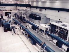
When completed, the National Ignition Facility (NIF) will house 192 laser beams the size of the prototype Beamlet (shown here) in a facility as big as a football stadium. Intended to perform fusion ignition and other experiments that will provide nuclear weapons reliability data, NIF will deliver as much as 1.8MJ/500TW in few-nanosecond pulses at 0.35 µm.
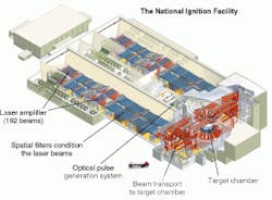
FIGURE 1. Facility design for NIF includes 192-beam laser amplifiers, spatial filters, and beam-transport system before target chamber.
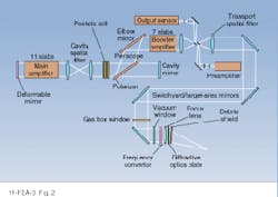
FIGURE 2. The NIF laser beamline architecture includes a preamplifier module, a booster amplifier, and a multipass main amplifier cavity for each of the 192 beamlines. More than 8000 large and 30,000 small precision optical components are required.
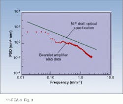
FIGURE 3. Optical surface requirements for mid-spatial frequency errors (periods from 33 to 0.12 mm) are defined by a power spectral density function (line). Data points show the mid-spatial frequency roughness for the laser slabs of NIF prototype Beamlet.
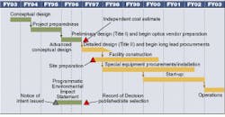
FIGURE 4. Fiscal Year 1996 activities culminate in major critical-path milestones that launch the construction phase of the NIF Project, scheduled to begin in FY 1997.
William J. Hogan is Senior NIF Scientist, L. Jeffrey Atherton is Associate Project Leader/Laser Material and Optical Technology for NIF, and Jeffrey A. Paisner is NIF Project Manager, Lawrence Livermore National Laboratory, POB 808, Livermore, CA 94551.