Rapid prototyping produces micron-sized parts
MICROFABRICATION
Conventional stereolithography systems build three-dimensional (3-D) physical representations of computer-aided design (CAD) images by scanning a focused laser beam across a vat of liquid polymer and solidifying it slice by slice into the required shape. Historically, these systems have had certain limitations in the feature size they could produce. While at least one vendor offers systems with resolution as small as 25 ?m, cost grows proportionally with required feature resolution.
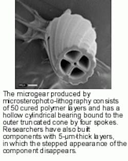
Chris Chatwin and colleagues at the school of engineering, University of Sussex (Brighton, England), have developed another option-microstereophotolithography in a project funded by the Engineering and Physical Sciences Research Council (Swindon, England). The technique reportedly can produce parts with complex micron-sized shapes that are either impossible or difficult to duplicate with conventional stereolithography or silicon-processing methods (see photo).1
The system operates in the ultraviolet (UV), as do conventional systems. One benefit is that it can use off-the-shelf polymers. There are several key differences between the microsterophotolithography system and commercial technology, though. One is that the system uses a spatial light modulator developed at CRL Smectec Technologies (Hayes, Middlesex, England) as a dynamic lithographic mask. This device is, in essence, the critical interface between the electronic and UV optical systems. Other major components include a CAD environment supporting solid or surface modeling, a resin bath with an integrated high-resolution translation stage and a component-building platform, a Spectra-Physics (Mountain View, CA) argon-ion laser with a power of 700 mW at 351.1 nm, an optical shutter, a diffractive optical element, a multielement lithographic reduction lens system, and a comprehensive control system.
Processing begins with the computer software sectioning a 3-D solid or surface model of the required components into layers, with the two-dimensional slices made at uniform increments along the chosen axis. Each slice is then converted to a bit-map format and loaded onto the spatial light modulator, which modulates the UV laser beam with the sliced image section. The multielement lens reduces the image 10 to 20 times and reimages it to the plane of the resin surface.
Component formation occurs in the resin bath. The researchers selected both the photopolymer and incident light so that the light produces cationic polymerization and initiates selective curing of the illuminated regions of the resin. A shutter in the beam`s path controls exposure time. Once a layer is cured, the build platform that it sits on is lowered into the bath, and new resin flows over the cured slice. The platform is then raised again until only the required thickness of resin covers the cured section, and processing repeats until the component is complete.
Unlike conventional stereolitho graphy devices, the microstereophotolithography system uses a planar layer-by-layer process of exposure. Chatwin and colleagues-including Maria Farsari, Shiping Huang, Rupert Yong, and Frederic Claret-Tournier-believe this approach has a major advantage over other methods because it cures layers concurrently over their entire surface, as opposed to incrementally building the layers themselves by curing layer sections as the laser beam traces them.

